Self-lock type zip head

A zipper puller and self-locking technology, which is applied in the field of zipper pullers, can solve the problems of increasing the difficulty of zipper puller assembly, difficulty in positioning, and failure to effectively fix the holding shrapnel, so as to facilitate automatic mechanical assembly, reduce assembly difficulty, and self-locking firm effect

Inactive Publication Date: 2010-02-17
FUJIAN SBS ZIPPER SCI & TECH CO LTD
View PDF6 Cites 0 Cited by
  • Summary
  • Abstract
  • Description
  • Claims
  • Application Information

AI Technical Summary

Problems solved by technology

[0003] However, since the resisting elastic piece is only limited between the cap and the brake hook, and is not effectively fixed, the problem that the resisting elastic piece cannot effectively provide elastic force due to movement in the cap may arise.
Moreover, since the resisting elastic piece is not effectively fixed, it is difficult to carry out automatic mechanical assembly
In addition, since the zipper puller needs to use a separate brake hook piece, and the brake hook piece is small in size and difficult to locate, thus further increasing the difficulty of assembling the zipper puller

Method used


Image

  • Self-lock type zip head
  • Self-lock type zip head
  • Self-lock type zip head

Examples


Embodiment Construction

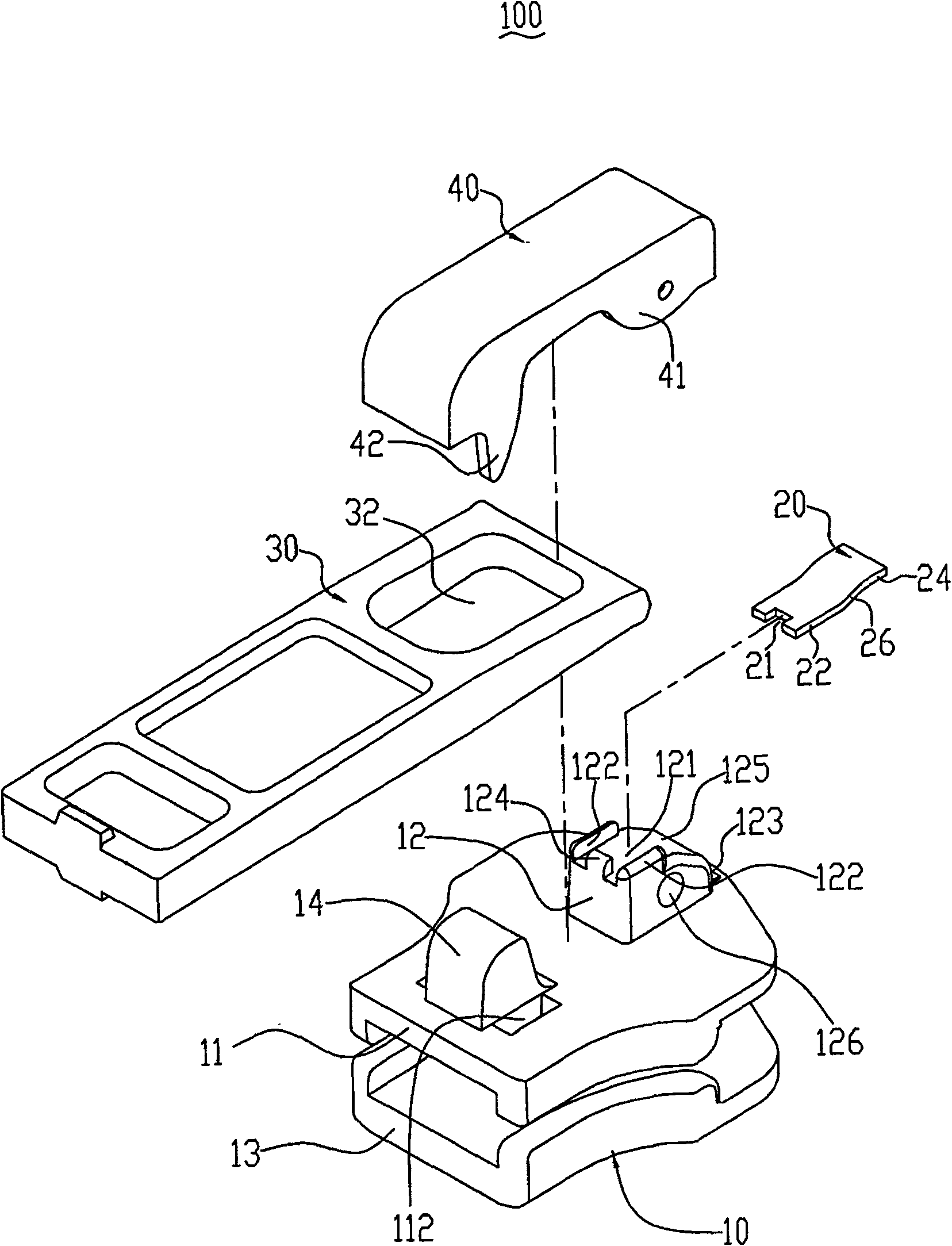
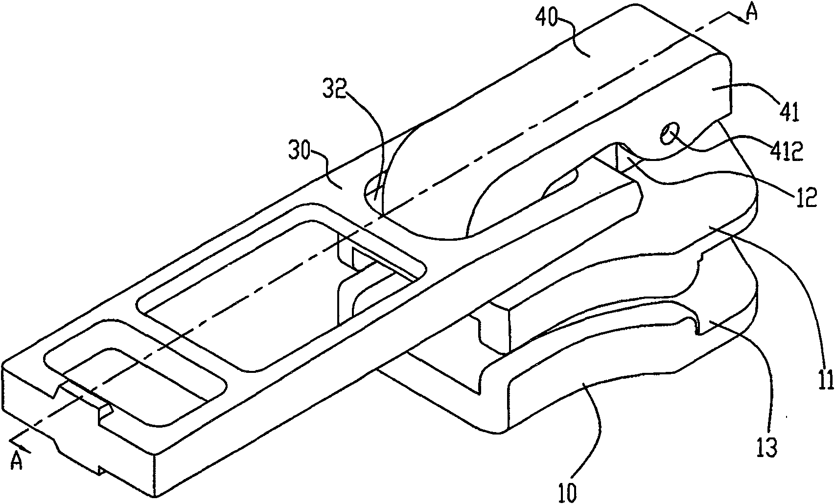
[0015] figure 1 Shown is a three-dimensional exploded view of the self-locking zipper puller 100 according to the first embodiment of the present invention. The zipper slider 100 includes a slider 10 , an elastic piece 20 , a pull piece 30 and a cap 40 . The elastic piece 20 and the cap 40 are respectively fixed on the slider 10 , and the pull piece 30 is sleeved on the cap 40 .

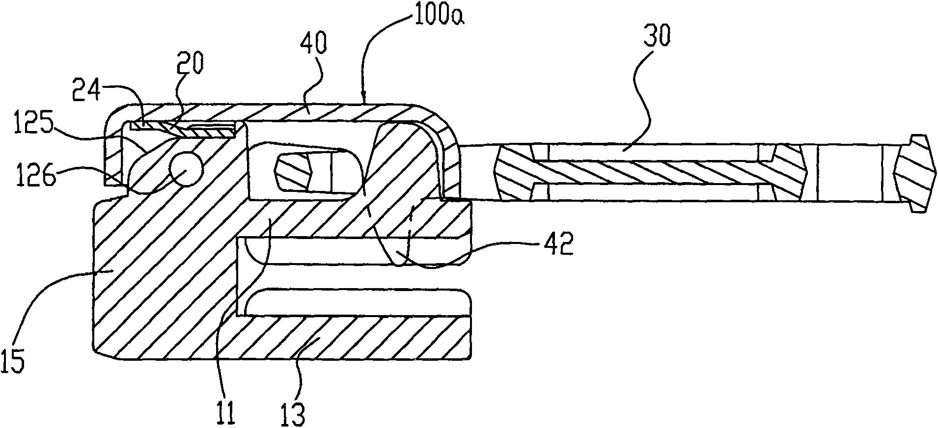
[0016] The slider 10 is made of metal material, and includes an upper wing 11 and a lower wing 13 . Connect by a guide post 15 between this upper wing plate 11 and the lower wing plate 13 (as image 3 shown), so as to form a substantially Y-shaped slideway for the chain teeth (not shown) of a zipper to pass through. The upper wing 11 is provided with a connecting block 12 , a limiting block 14 and a through hole 112 . The connecting block 12 is located at the front end of the upper wing plate 11 , and the limiting block 14 and the through hole 112 are located at the rear end of the upper wing pla...


PUM


Abstract

The invention relates to a self-lock slide fastener head, which comprises a slide block, an elastic piece, a pulling piece and a cap cover, wherein the pulling piece is sleeved on the cap cover; the slide block is provided with a connecting block and a through hole; the front end of the cap cover is pivoted on the connecting block; the rear end of the cap cover is provided with a buckle piece; thebuckle piece is inserted in the through hole of the slide block; and one end of the elastic piece is connected with the connecting block, while the other end is contacted with the cap cover to applyelastic force on the cap cover. The slide fastener head has the advantages of stable structure, firm self locking, fewer required elements, and favorability for mechanical automatic assembly.

Description

technical field [0001] The invention relates to a zipper puller, in particular to a self-locking zipper puller. Background technique [0002] Existing zipper sliders can be roughly divided into self-locking zipper sliders and non-self-locking zipper sliders. Non-self-locking zipper sliders may slide along the zipper tape under non-human conditions, while self-locking zipper sliders can prevent sliding under non-human operating conditions through a specially designed self-locking mechanism. The Chinese utility model patent No. 02285335.9 announced on December 10, 2003 discloses a self-locking zipper puller, which includes a zipper puller body, a brake hook piece, a set of resisting elastic pieces and a cap. The end surface of the zipper slider body is provided with a fitting part and a slot, the cap is fixed on the fitting part, and the braking hook is embedded in the slot. A resisting elastic piece is placed between the inner wall of the cap and the upper end surface of th...

Claims


Application Information

Patent Timeline
Patent Type & Authority Patents(China)
IPC IPC(8): A44B19/26
Inventor 高秀忠李鹏辉
Owner FUJIAN SBS ZIPPER SCI & TECH CO LTD
Why Eureka
Try Eureka