
Water-cooling head structure

A technology of water cooling head and heat exchange device, which is applied in the direction of cooling/ventilation/heating transformation, instrumentation, electrical digital data processing, etc., and can solve the problems of reducing the volume of water cooling and heat dissipation systems, reducing volume, etc.

Inactive Publication Date: 2010-02-24
COOLER MASTER CO LTD +1
View PDF6 Cites 1 Cited by
  • Summary
  • Abstract
  • Description
  • Claims
  • Application Information

AI Technical Summary

Problems solved by technology

[0005] In order to solve the problem of space requirement in the prior art, the water-cooling head and the pump of the water-cooling system are combined with each other, so that the water-cooling head device not only has the function of absorbing heat, but also has a driving force inside the water-cooling head. The power of the working fluid exists to reduce the volume required by the water cooling system; however, due to the limitation of the traditional pump structure that uses the fan blade structure as the power source, even if the mutual structure of the water cooling head and the pump can reduce one component, the combined The water-cooling head device cannot greatly reduce the volume requirements. In order to meet the needs of many electronic products for water-cooling systems, it is necessary to find another solution to improve the existing problems.

Method used


Image

  • Water-cooling head structure
  • Water-cooling head structure
  • Water-cooling head structure

Examples


Embodiment Construction

[0018] The above and other technical features and advantages of the present invention will be described in more detail below in conjunction with the accompanying drawings.

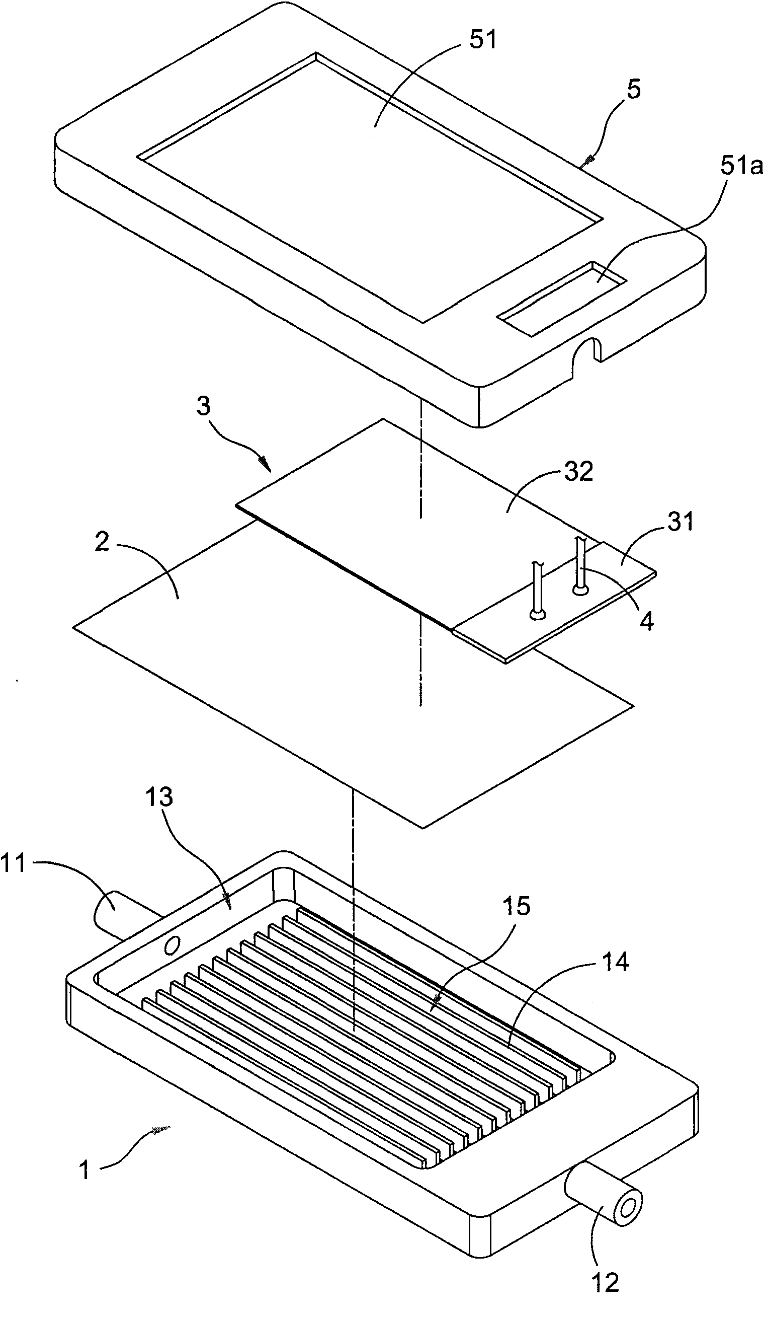
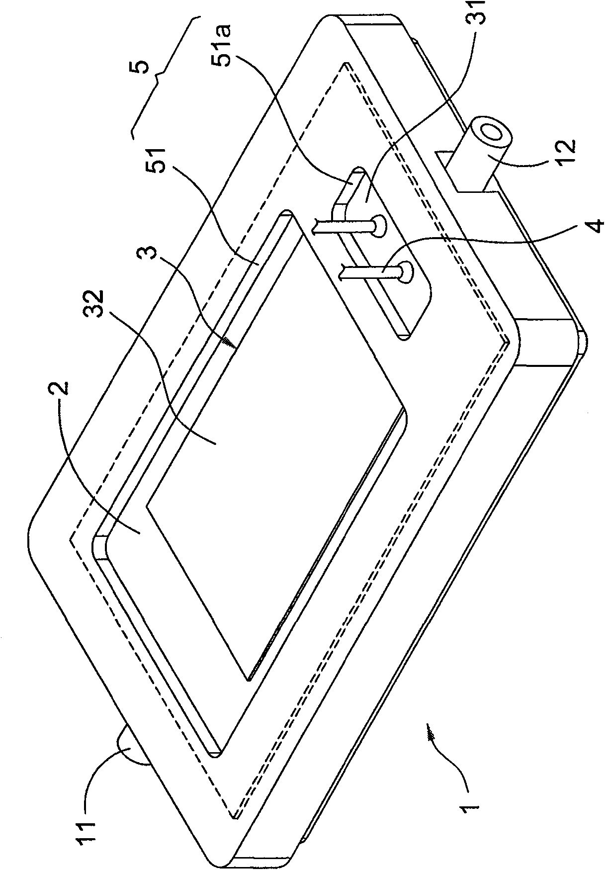
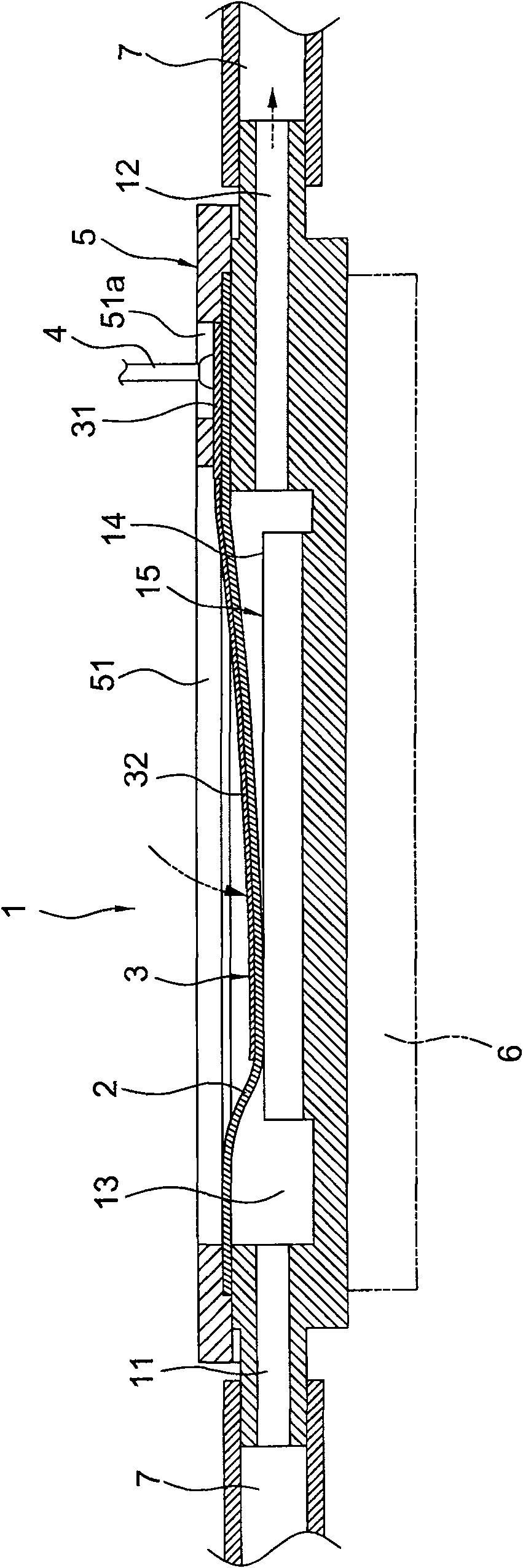
[0019] see figure 1 and figure 2 , is the three-dimensional structure exploded view and combined completed view of the present invention. As shown in the figure, the water cooling head of the present invention is mainly based on a cavity 1, and the left and right sides of the cavity 1 are respectively provided with a water inlet pipe 11 and a water outlet pipe 12, and in the cavity 11 The inside is provided with a chamber 13, and the chamber 13 is connected with the water inlet pipe 11 and the water outlet pipe 12 respectively; and a heat exchange device 14 is arranged in the chamber 13, wherein the The heat exchanging device 14 is composed of a plurality of cooling fins arranged at intervals, and any two adjacent cooling fins form a cooling channel 15 .

[0020] continued see figure 1 , a film 2 is a...


PUM


Abstract

The invention relates to a water block structure used to be attached on a heating element. The structure mainly comprises a cavity, wherein, the cavity is provided with a chamber inside; one side or two sides of the cavity is respectively provided with a water inlet pipe and a water outlet pipe which are communicated with the chamber; the chamber is provided with a heat exchange structure inside for heat exchange with working fluid; the top of the cavity is provided with a film which is provided with an actuating element for driving the film to swing up and down so as to oppress the working fluid in the chamber to circularly flow in a single direction; the actuating element is taken as a power source, and simultaneously the water block is made to have a thin structure.

Description

technical field [0001] The invention relates to a heat dissipation device, in particular to a water cooling head device for attaching heating elements. Background technique [0002] In today's technology industry, the development of products tends to be more sophisticated. In addition to the miniaturization of the volume, the heat generation is also increasing. Especially in the computer, due to the continuous improvement of its computing performance and the increase of peripheral electronic components, the overall development of the computer The heat is also greatly increased. Therefore, in order to allow the computer to operate normally within the allowable operating temperature range, an additional cooling device must be used to reduce the adverse effects of heat on the operation of the computer. [0003] As far as the heat dissipation devices currently used, in addition to the fan being the most convenient and widely used heat dissipation device, the water-cooled heat di...

Claims


Application Information

Patent Timeline
Patent Type & Authority Patents(China)
IPC IPC(8): H05K7/20G06F1/20H01L23/473
CPCH01L2924/0002
Inventor 马小康彭昌宏侯博仁郭明健
Owner COOLER MASTER CO LTD
Learn More