

Steam gas supply system
A technology of steam supply system and steam curing, which is applied in pipeline system, mechanical equipment, gas/liquid distribution and storage, etc. It can solve problems such as waste of energy, pipeline vibration, damage, etc., to save energy, prevent pipeline damage, The effect of avoiding water hammer phenomenon
- Summary
- Abstract
- Description
- Claims
- Application Information
AI Technical Summary
Problems solved by technology
Method used
Image

Examples
Embodiment Construction
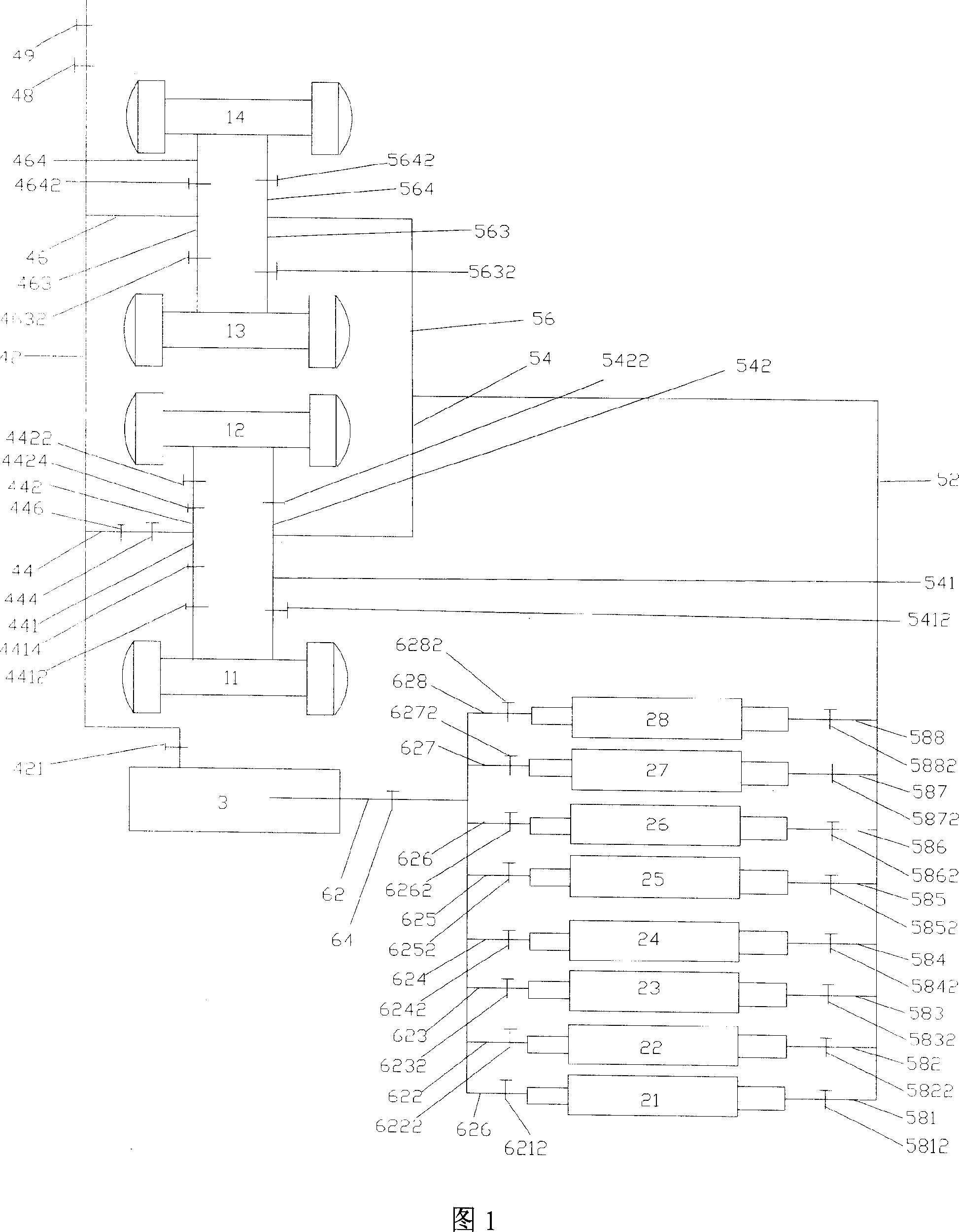
[0009] Please refer to Figure 1, a steam-curing steam supply system, including four autoclaves, respectively 1# kettle 11, 2# kettle 12, 3# kettle 13, 4# kettle 14, and eight steam-curing pools, respectively These are 1# Pool 21, 2# Pool 22, 3# Pool 23, 4# Pool 24, 5# Pool 25, 6# Pool 26, 7# Pool 27, and 8# Pool 28.
[0010] A steam supply main pipe 42 is provided from the sub-cylinder 3 of the boiler room to the four autoclaves, and a steam supply main valve 421 is installed at the front end of the steam supply main pipe 42 . The middle of the steam supply main pipe 42 is successively connected with a first steam supply branch pipe 44 and a second steam supply branch pipe 46 . A stop valve 48 and a drain valve 49 are provided at the end of the steam supply main pipe 42 . Branch out a first steam supply branch pipe 441 leading into the 1# kettle 11 and a second steam supply branch pipe 442 leading into the 2# kettle 12 from the first steam supply branch pipe 44 . Branch out ...
PUM
 Abstract
Description
Claims
Application Information