
Conveyance apparatus with lifting/lowering load carrying platform

A conveying device and racking technology, which is applied in the direction of lifting frame, lifting device, manual conveying device, etc., can solve the problems such as the design of the walking body that cannot be transported, the inability to lower the top surface, and the increase in height.

Active Publication Date: 2007-07-18
DAIFUKU CO LTD
View PDF1 Cites 15 Cited by
  • Summary
  • Abstract
  • Description
  • Claims
  • Application Information

AI Technical Summary

Problems solved by technology

[0004] In the conveying device with the above structure, the jack-up operation position generated by the elevating member relative to the cross link is used as the central cross fulcrum position of the cross link, or by a link that is closer to the conveying body side than the central cross fulcrum position. The position of the fulcrum of the rod can make the rising stroke of the shelf greater than the rising stroke of the lifting part, but in this way, in order to increase the rising stroke of the shelf and fully increase the height of its rising position, the rising stroke of the lifting part must be increased accordingly. As a result, the following problems will occur: not only the height of the lower protruding part of the above-mentioned elevating member on the conveyance running body increases, but also the height of the cam rail laid on the floor surface on the conveyance path side increases, so that the conveyance cannot be lowered. The top surface of the body (the working ground on the walking body for transportation), that is, the walking body for transportation cannot be designed as a low table structure

Method used


Image

  • Conveyance apparatus with lifting/lowering load carrying platform
  • Conveyance apparatus with lifting/lowering load carrying platform
  • Conveyance apparatus with lifting/lowering load carrying platform

Examples


Embodiment Construction

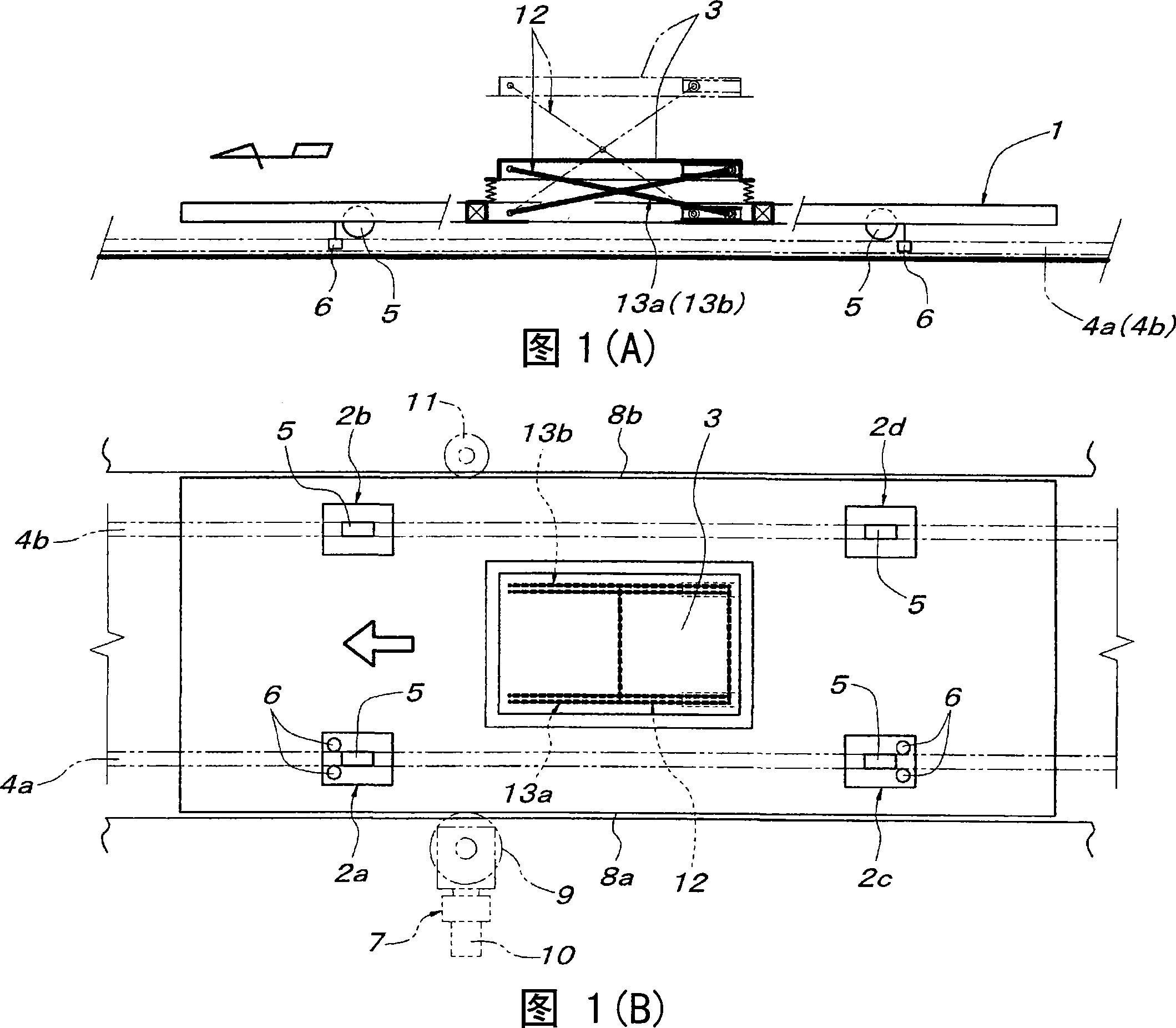
[0023] Below, specific embodiments of the present invention will be described according to the accompanying drawings. Fig. 1 shows the basic structure of a transport device with a friction-driven form of a shelf that can be lifted. The walking body for transportation has a left and right pair of front and rear wheel assemblies 2a-2d and a liftable shelf 3. Each wheel unit 2a-2d has a wheel 5 rolling on a pair of left and right guide rails 4a, 4b laid along the transport path, and is provided on the front and rear two wheel units 2a, 2c on the left and right sides (the left side in the illustration). There are vibration-proof vertical axis rollers 6 sandwiching the guide rail 4a from both left and right sides. The traveling body 1 for transportation is propelled by a friction drive mechanism 7 provided at an appropriate point in the transportation path. The friction drive mechanism 7 is a conventionally known technology, and it is composed of a drive friction wheel 9, a motor ...


PUM


Abstract

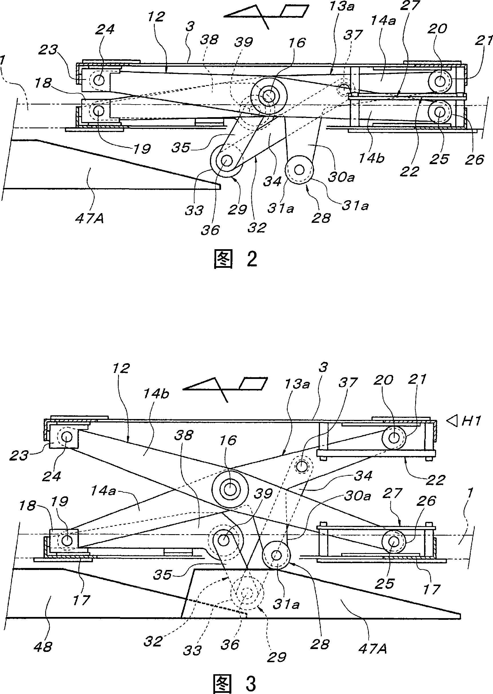
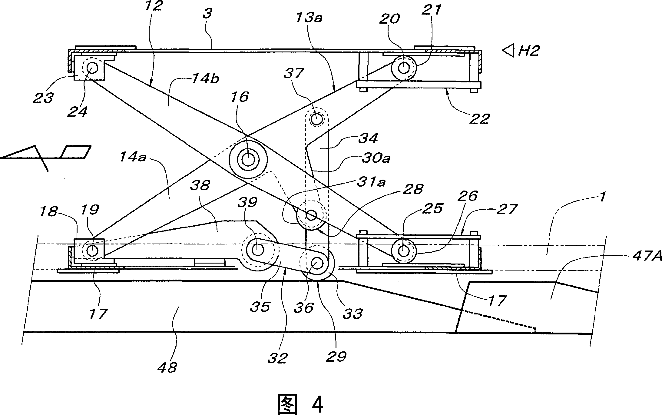
A lifting stroke of a load carrying platform (3), liftably / lowerably supported through a cross link (13a), of a traveling body (1) for conveyance is increased with a low floor structure of the traveling body (1) maintained. In a conveyance apparatus having a lifting / lowering load carrying platform, there are laid a first cam rail (47A) acting on a first to-be-operated section (28) to lift a load carrying platform (3) to an intermediate height (H1) and a second cam rail (48) acting on a second to-be-operated section (29) to lift the platform (3) from the intermediate height (H1) to the maximum height (H2). The second to-be-operated section (29) is provided at an intermediate folding fulcrum (36) of a toggle link (32) interposed between the cross link (13a) and a fixation position on the traveling body (1) side. When the platform (3) is lifted to the intermediate height (H1), the toggle link (32) is extended such that both upper fulcrums (37, 39) are separated, relative to the intermediate folding fulcrum (36), to both the front and rear in the traveling direction. The second to-be-operated section (29) in this extended state of the toggle link (32) is positioned below the first to-be-operated section (28) in the same state.

Description

technical field [0001] The invention relates to a conveying device. The conveying device converts a shelf to a raised position through a cam rail laid on the side of a conveying path. The shelf is supported on a conveying walking body in a liftable manner through a cross link that can rise and fall. Background technique [0002] As described in Patent Document 1, this conveying device is provided with a cross link that supports the shelf in a liftable manner, and an elevating member that lifts the cross link by moving up and down to make it stand up constitutes the operated part. , push up the lifting part on the cam rail on the side of the conveying path to raise the shelf. [0003] Patent Document 1: Japanese Patent Application Laid-Open No. 7-172538 Contents of the invention [0004] In the conveying device with the above structure, the jack-up operation position generated by the elevating member relative to the cross link is used as the central cross fulcrum position ...

Claims


Application Information

Patent Timeline
Patent Type & Authority Applications(China)
IPC IPC(8): B65G17/06B62D65/18B65G17/48B66F7/06
CPCB66F7/065B62D65/18B65G7/02B65G17/48
Inventor 林信浩
Owner DAIFUKU CO LTD
Learn More