
Wafer bonding method and wafer bonding structure

A wafer bonding and wafer technology, applied in the field of microelectronics, can solve problems such as poor wafer bonding, and achieve the effect of avoiding poor bonding

Inactive Publication Date: 2020-10-02
SEMICON MFG ELECTRONICS (SHAOXING) CORP
View PDF7 Cites 0 Cited by
  • Summary
  • Abstract
  • Description
  • Claims
  • Application Information

AI Technical Summary

Problems solved by technology

[0006] The purpose of the present invention is to provide a wafer bonding method to solve the problem of poor bonding of wafers bonded to each other in the middle region of the existing bonding process

Method used


Image

  • Wafer bonding method and wafer bonding structure
  • Wafer bonding method and wafer bonding structure
  • Wafer bonding method and wafer bonding structure

Examples


Embodiment Construction

[0039] As mentioned in the background, in the prior art, when the wafers to be bonded are directly bonded, the surface warping of the wafers often leads to poor bonding quality of the wafers.

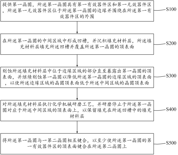
[0040] For this reason, the present invention provides a kind of bonding method of wafer, specifically refer to figure 2 , figure 2 It is a schematic flow chart of a wafer bonding method in an embodiment of the present invention, and the bonding method includes:

[0041] Step S100, providing a first wafer, the first wafer has a middle region and an edge region, and the edge region surrounds the periphery of the middle region;

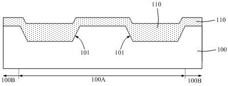
[0042] Step S200, forming a groove in the middle region of the first wafer, and depositing a filling material layer, the filling material layer filling the groove and covering the top surface of the first wafer;

[0043] Step S300, etching the part of the filling material layer located in the edge region until the top surface of the first wafer is exposed, an...


PUM


Abstract

The invention provides a wafer bonding method and a wafer bonding structure. Before a chemical mechanical polishing process is performed, the top surface of the edge region of a first wafer is lowered, so that when the chemical mechanical polishing process is executed, the top surface of the middle area of the polished first wafer is not lower than the top surface of the edge area of the first wafer, and when a bonding process is executed, the problem of poor bonding of the middle area of the wafer caused by mutual contact of the overhigh upwarp wafer edges can be effectively avoided.

Description

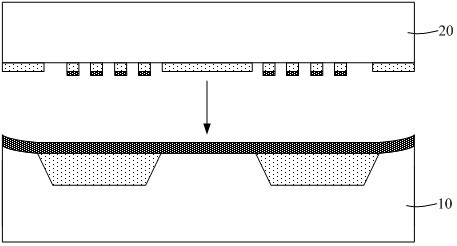
technical field [0001] The invention relates to the technical field of microelectronics, in particular to a wafer bonding method and bonding structure. Background technique [0002] Wafer bonding technology is to closely bond two wafers under predetermined conditions. This technology is widely used in the field of microelectronics manufacturing. For example, in the processing technology of micro-electromechanical systems, the wafer bonding process can be used Realize the processing of micro-mechanical structures. Among them, the quality of the bonding process will directly affect the performance of the formed semiconductor device. Specifically, the morphology of the bonding surfaces of the two wafers bonded to each other is an important factor affecting the quality of the wafer bonding process. [0003] figure 1 It is a structural schematic diagram of an existing wafer bonding process, such as figure 1 As shown, a first wafer 10 and a second wafer 20 to be bonded are pro...

Claims


Application Information

Patent Timeline
Patent Type & Authority Applications(China)
IPC IPC(8): H01L21/18H01L23/48
CPCH01L21/185H01L23/48H01L24/02H01L24/03H01L24/04
Inventor 穆苑龙王冲
Owner SEMICON MFG ELECTRONICS (SHAOXING) CORP
Learn More