
Semiconductor structure and method for forming same

a semiconductor and structure technology, applied in the field of semiconductor structure and a forming method, can solve the problems of inadequate performance of the formed device, achieve the effects of reducing the number of contact surfaces, avoiding contact with the top surface, and improving the performance of the semiconductor structur

Pending Publication Date: 2022-09-15
SEMICON MFG NORTH CHINA (BEIJING) CORP
View PDF0 Cites 0 Cited by
  • Summary
  • Abstract
  • Description
  • Claims
  • Application Information

AI Technical Summary

Benefits of technology

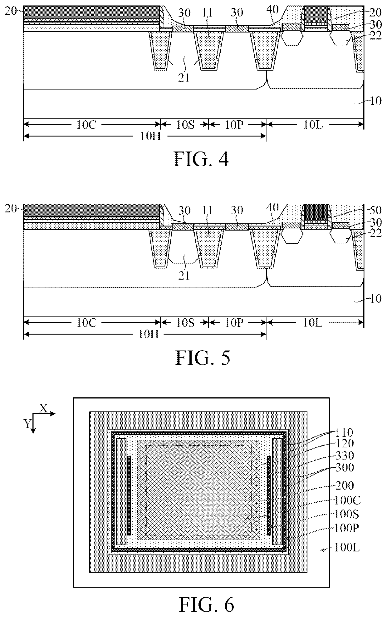
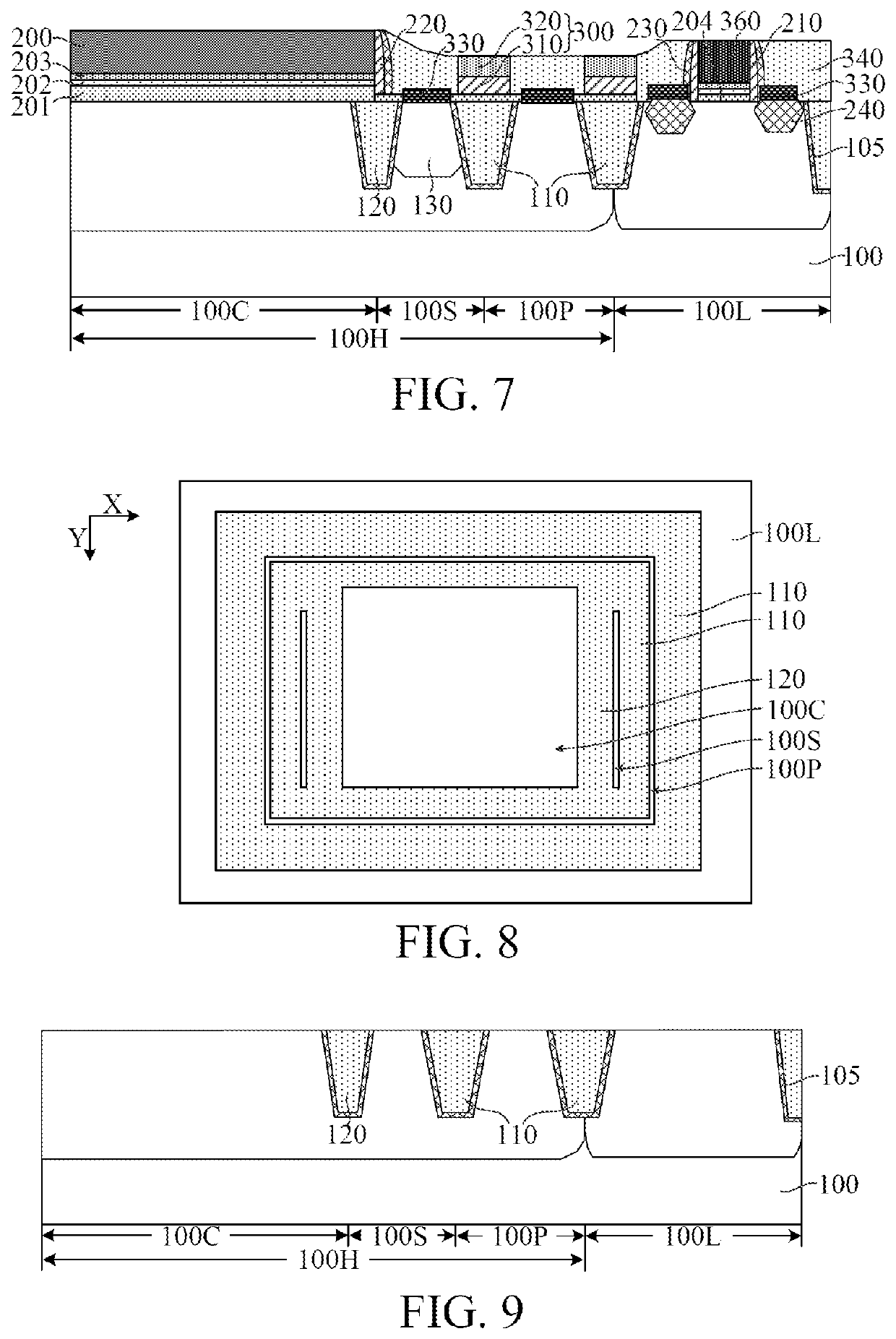
The present disclosure provides a semiconductor structure and a method for forming it that can address the problem of top surface dishing during the planarization process of forming the interlayer dielectric layer and the metal gate, and also protect the first source / drain doping region and the well pick-up region from contacting during the planarization process. The technical effect of this patent is the improvement of the performance of the semiconductor structure and the yield of production and manufacturing.

Problems solved by technology

However, at present, formed devices have inadequate performance.

Method used


Image

  • Semiconductor structure and method for forming same
  • Semiconductor structure and method for forming same
  • Semiconductor structure and method for forming same

Examples


Embodiment Construction

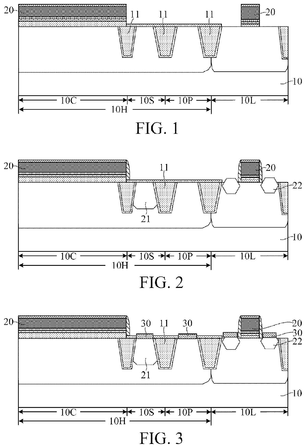
[0017]As can be seen from the prior art, at present, the performance of semiconductor structures need to be improved. Reasons why the performance of semiconductor structures need to be improved are now analyzed in combination with a method for forming a semiconductor structure. FIG. 1 to FIG. 5 are schematic structural diagrams corresponding to steps in a method for forming a semiconductor structure.

[0018]Referring to FIG. 1, a base 10 is provided, including a first device region 10H used for forming a first device and a second device region 10L used for forming a second device. A channel length of the first device is greater than a channel length of the second device. The base 10 in the first device region 10H includes a channel region 10C, preset regions 10S located on two sides of the channel region 10C in a length direction of the channel region 10C and used for forming a first source / drain doping region, and a well pick-up region 10P surrounding the channel region 10C and the p...


PUM

PropertyMeasurementUnit
widthaaaaaaaaaa
voltageaaaaaaaaaa
ultralow voltageaaaaaaaaaa

Abstract

Semiconductor structures and methods for forming same are disclosed. In one form, a structure includes: a base, including a first device region and a second device region, where the first device region includes a channel region, and preset regions located on two sides of the channel region, and a well pick-up region surrounding the channel region and the preset regions; a first isolation structure, located in the base between the preset regions and the well pick-up region and between the well pick-up region and the adjacent second device region; a poly gate, covering the channel region; a first source / drain doping region, located in the preset regions on two sides of the poly gate; a metal gate, located on the base in the second device region; a support structure, located on the top of the first isolation structure; and an interlayer dielectric layer, covering side walls of the poly gate, the metal gate, and the support structure. The support structure can mitigate a problem of top surface dishing of the interlayer dielectric layer above the first isolation structure, to avoid contacting the first source / drain doping region and the well pick-up region in a planarization process of forming the interlayer dielectric layer and the metal gate, thereby improving the performance of the semiconductor structure.

Description

RELATED APPLICATIONS[0001]The present application claims priority to Chinese Patent Appln. No. 202110269371.X, filed Mar. 12, 2021, the entire disclosure of which is hereby incorporated by reference.BACKGROUNDTechnical Field[0002]Embodiments of the present disclosure relate to the field of semiconductor manufacturing, and in particular, to a semiconductor structure and a method for forming same.Related Art[0003]In semiconductor technologies, even as the size of elements continue to decrease, it is still expected that a performance of transistors can be further enhanced, and it is also expected that an integrated circuit (IC) semiconductor apparatus that combines low voltage (LV), medium voltage (MV), high voltage (HV) application ranges can be manufactured.[0004]For example, an IC used for driving an image sensor, a liquid crystal display (LCD), or a magnetic printing head (referred to as a driver IC hereinafter) is formed by a driver output unit having an HV metal-oxide semiconduct...

Claims


Application Information

Patent Timeline
Patent Type & Authority Applications(United States)
IPC IPC(8): H01L27/088H01L29/45H01L29/66H01L21/285H01L21/8234
CPCH01L27/088H01L29/45H01L29/665H01L29/66545H01L21/28518H01L21/823418H01L21/823481H01L29/0603H01L29/0615H01L29/0684H01L27/0203H01L21/76819H01L23/53295H01L21/76224H01L29/78H01L29/0653H01L29/66636H01L29/7848H01L29/165H01L29/6656H01L29/66568H01L27/0922H01L21/823475H01L21/823493H01L21/823878
Inventor QIAOMING, CAILISHA, MA
Owner SEMICON MFG NORTH CHINA (BEIJING) CORP
Learn More