Manufacturing method of semiconductor device, manufacturing method of electronic device
a manufacturing method and semiconductor technology, applied in semiconductor devices, solid-state devices, basic electric elements, etc., can solve problems such as deteriorating the sealing performance of semiconductor chips, and achieve the effects of improving the sealing performance of electronic components, suppressing the occurrence of voids, and increasing resin injection pressur
- Summary
- Abstract
- Description
- Claims
- Application Information
AI Technical Summary
Benefits of technology
Problems solved by technology
Method used
Image
Examples
first embodiment
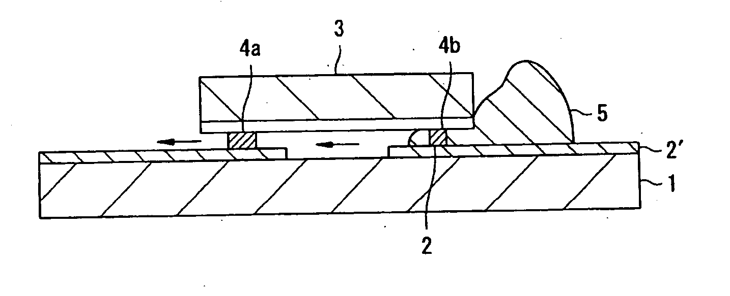
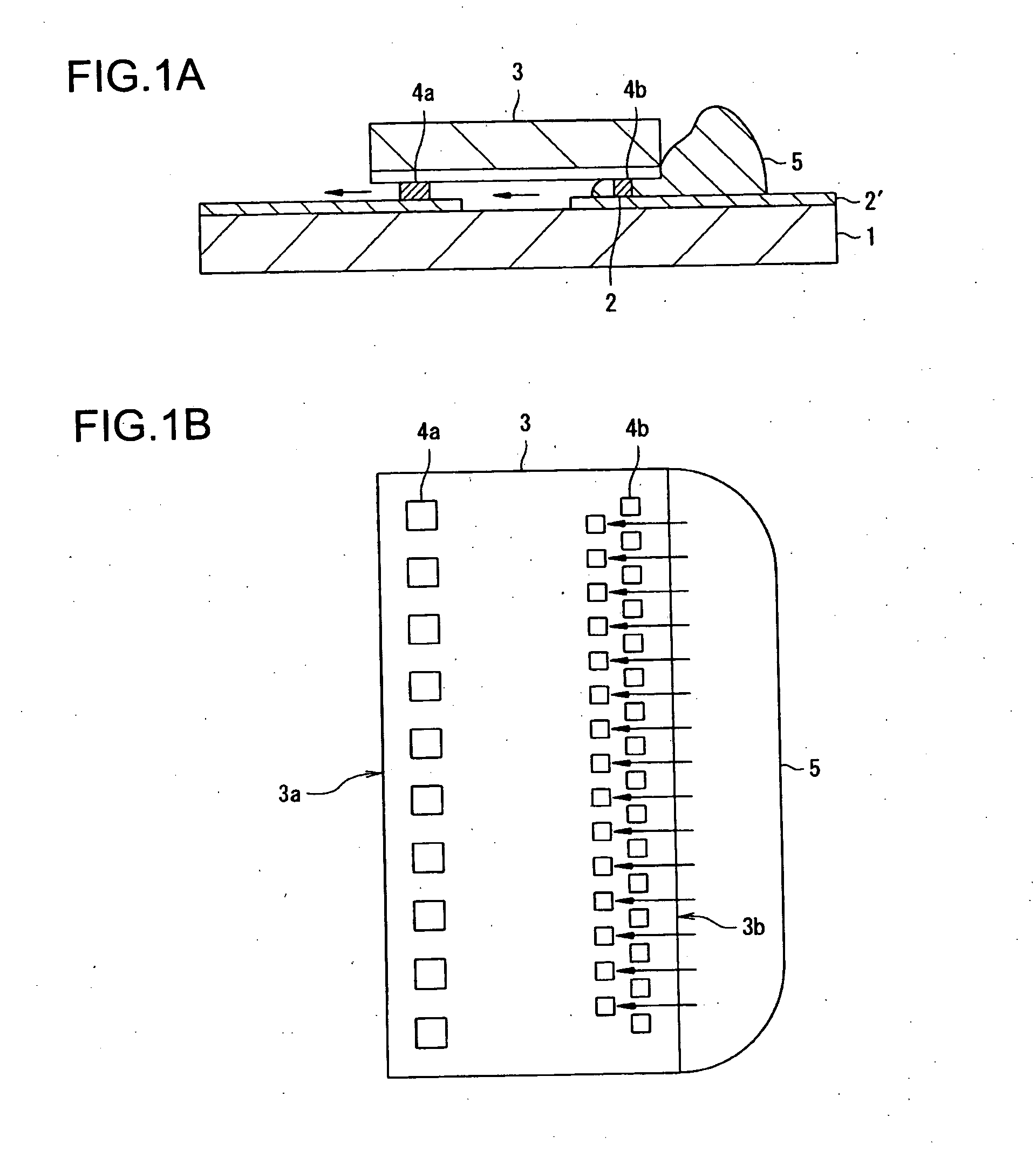
[0029]FIG. 1(a) is a sectional view showing a manufacturing method of a semiconductor device of the invention. FIG. 1(b) is a plan view showing a flow of a sealing resin 5 on a semiconductor chip 3 shown in FIG. 1(a).
[0030] In FIG. 1, a connecting terminal 2 is connected to the wiring portion 2′. Bump electrodes 4a and 4b are disposed on the semiconductor chip 3. The bump electrodes 4a are arrayed in a straight line along one long side 3a of the semiconductor chip 3 and the bump electrodes 4b are arrayed in a zigzag arrangement along the other long side 3b of the semiconductor chip 3.
[0031] The semiconductor chip 3 is subjected to face-down mounting in which the bump electrodes 4a and 4b are connected onto the wiring terminal 2. A surface of the semiconductor chip 3 is sealed by injecting the sealing resin 5 into the interstices between the semiconductor chip 3 and the film substrate 1. Here, it is possible to carry out the injection of the sealing resin 5 from the long side 3b alo...
second embodiment
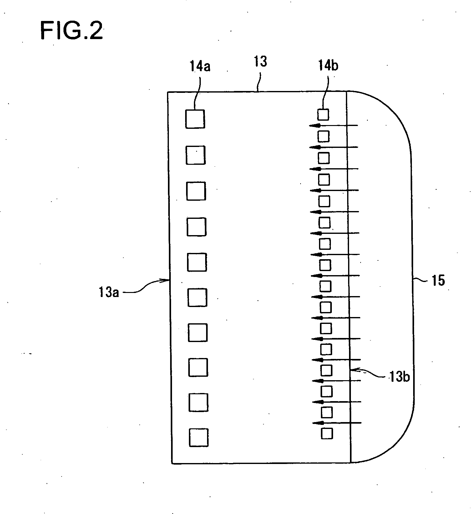
[0034]FIG. 2 is a plan view showing a flow of a sealing resin 15 on a semiconductor chip 13 of the invention.
[0035] In FIG. 2, bump electrodes 14a and 14b are disposed on the semiconductor 13. Each bump electrode array 14a and 14b is respectively arranged in a straight line along a long side 13a or 13b opposing each other on the semiconductor chip 13. A spacing between the bump electrodes 14b in the array is narrower than that of the bump electrodes 14a. Here, it is possible to carry out the injection of the sealing resin 15 from the long side 13b along which the bump electrodes 14b are arrayed to seal the surface of the semiconductor chip 13 that is subjected to face-down mounting via the bump electrodes 14a and 14b.
[0036] Accordingly, it is possible to increase an injection pressure of the sealing resin 15 at the array side of the bump electrodes 14b having a more narrow spacing than that of the bump electrodes 14a by adjusting an injecting direction of the sealing resin 15. Thus...
third embodiment
[0037]FIG. 3 is a plan view showing a flow of a sealing resin 25 on the semiconductor chip 23 of the invention.
[0038] In FIG. 3, bump electrodes 24a and 24b are disposed on the semiconductor chip 23. Here, the bump electrodes 24a are arrayed in a straight line along one long side 23a of the semiconductor chip 23 and the bump electrodes 24b are arrayed in a straight line along the other long side 23b and each short side 23c and 23d of the semiconductor chip 23. A spacing between the bump electrodes 24b in the array is narrower than that of the bump electrodes 24a. Here, it is possible to carry out the injection of the sealing resin 25 from the long side 23b along which the bump electrodes 24b are arrayed to seal the surface of the semiconductor chip 23 that is subjected to face-down mounting via the bump electrodes 24a and 24b.
[0039] Accordingly, it is possible to increase an injection pressure of the sealing resin 25 at the array side of the bump electrodes 24b having a more narrow...
PUM
 Abstract
Description
Claims
Application Information
 - R&D
- Intellectual Property
- Life Sciences
- Materials
- Tech Scout
- Unparalleled Data Quality
- Higher Quality Content
- 60% Fewer Hallucinations
Browse by: Latest US Patents, China's latest patents, Technical Efficacy Thesaurus, Application Domain, Technology Topic, Popular Technical Reports.
© 2025 PatSnap. All rights reserved.Legal|Privacy policy|Modern Slavery Act Transparency Statement|Sitemap|About US| Contact US: help@patsnap.com


