Spinning multistage mixed flow burner

A burner and mixed-flow technology, which is applied in the direction of burner, gas fuel burner, combustion method, etc., can solve the problems such as the difficulty of turning on the low fire of the burner, and achieve the effect of full combustion, simple and reasonable structure, and lower temperature

Inactive Publication Date: 2007-07-25
王战勇
View PDF1 Cites 3 Cited by
  • Summary
  • Abstract
  • Description
  • Claims
  • Application Information

AI Technical Summary

Problems solved by technology

But the burner has the disadvantage that it is difficult to open a small fire

Method used


Image

  • Spinning multistage mixed flow burner
  • Spinning multistage mixed flow burner
  • Spinning multistage mixed flow burner

Examples


Embodiment 1

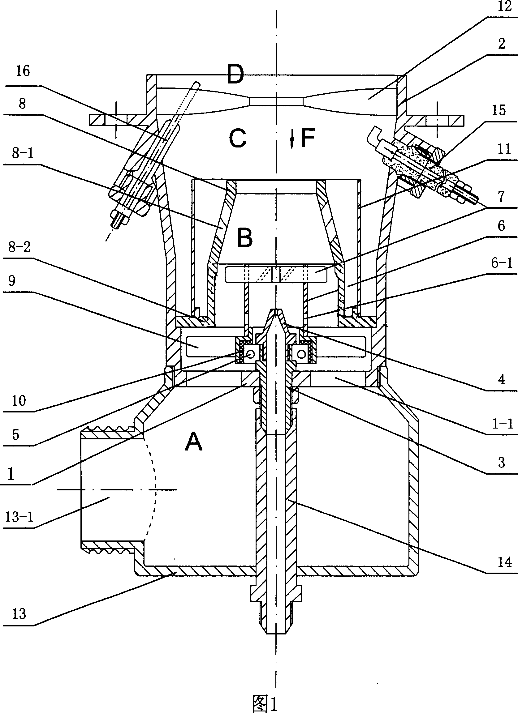
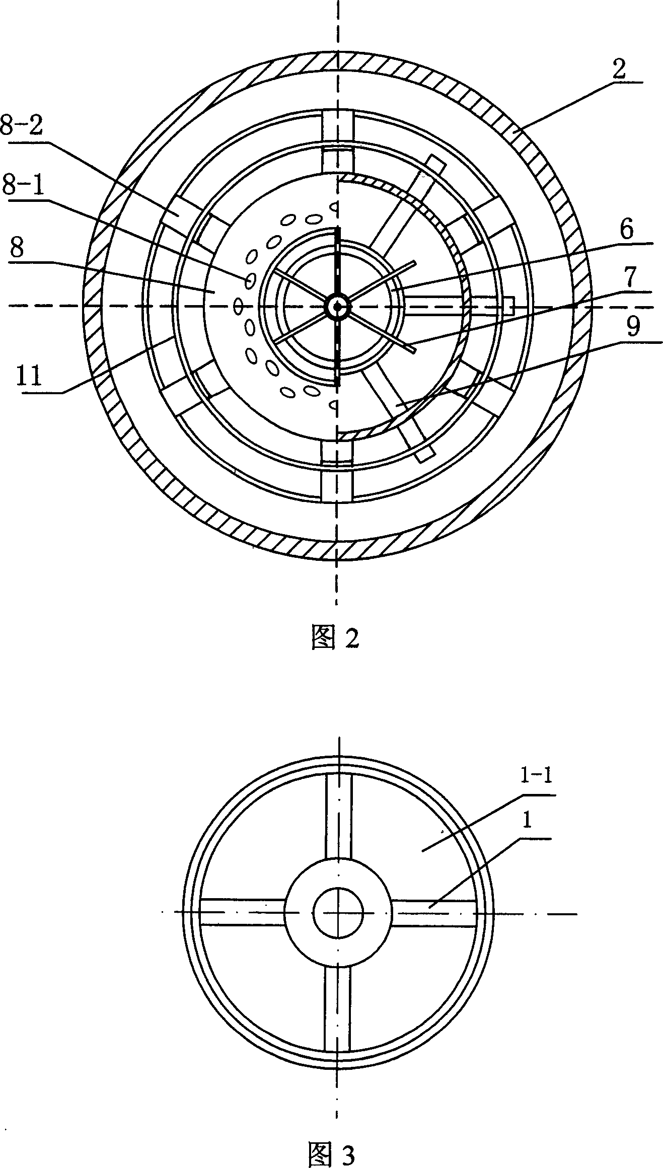
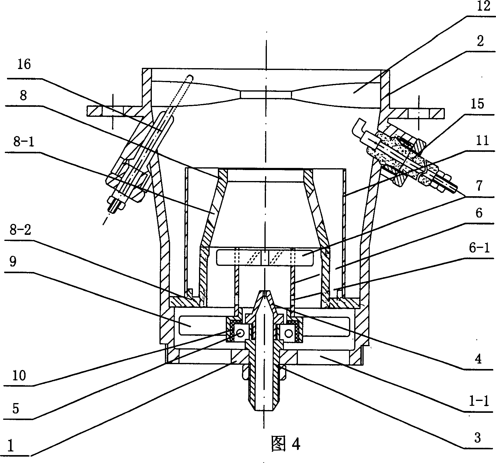
[0016] Example 1. See Figure 1 and Figure 2, this example is a two-stage mixed-flow burner with fan rotation, it has a shell 2 with a bottom plate 1, an igniter 15 and a flameout protector 16 are arranged inside the shell, and there are four fan-shaped air outlets 1 on the bottom plate -1 (see Figure 3). The central tube shaft 3 is fixed in the center of the bottom plate, and the center tube shaft body is provided with a bearing 5, and a heat-insulating bush 10 made of glass fiber material is arranged outside the bearing, and a rotor vane duct 6 is connected to the outer side of the heat-insulation bush. There are 6 upper wind blades 7 and lower wind blades 9 similar to electric fan blades respectively in the lower part; Inside the casing 2 there is a mixed-flow muffler cap 8 in the form of a few characters. The top of the muffler cap is open. Two rows of small holes 8-1 are arranged in a staggered arrangement on the wall of the cap. On the convex edge of the inner wall, the...

Embodiment 2

[0018] Example 2. As shown in Fig. 5, this example is a two-stage mixed-flow burner without fan rotation. Compared with Example 1, there is no air chamber 13 with a tuyere 13-1 at the shell-bottom portion, and no fuel connecting pipe 14 is provided. This example has a simple structure and a good combustion effect, and is especially suitable for night food stalls and families. The rest are the same as example 1.


PUM


Abstract

The present invention relates to an automatic rotary multi-stage mixed flow combustor. It includes the following several portions: a shell body with bottom plate, on the bottom plate a centre pipe shaft is set, on the bottom plate around the centre pipe shaft several air-feeding holes are set, the top portion of said pipe shaft is equipped with a nozzle, and the shaft body of said pipe shaft is equipped with a bearing; and said bearing is connected with a rotary vane conduct pipe. Besides, said invention also provides the working principle of said mixed flow combustor and its concrete operation method.

Description

technical field [0001] The invention relates to a burner for gas, in particular to a self-rotating multi-stage mixed-flow burner. Background technique [0002] In the prior art, there is also a class of relatively high-power burners, which generally require two large and small Venturi tubes and valves with two holes to adjust the large and small fires. High enough. Chinese patent CN1563794A discloses a "shaft center oil supply burner", which has a shell with a bottom plate, a central tube shaft on the bottom plate, through holes on the bottom plate around the tube shaft, nozzles on the top of the tube shaft, and a nozzle on the top of the tube shaft. The shaft body is provided with bearings. But this burner has the deficiency that it is difficult to open a small fire. Contents of the invention [0003] The technical problem to be solved by the present invention is to simplify the structure and use a single-hole valve to realize the adjustment of large and small fires, a...

Claims


Application Information

Patent Timeline
Patent Type & Authority Applications(China)
IPC IPC(8): F23D14/64F23D14/02
Inventor 王战勇
Owner 王战勇
Why Eureka
Try Eureka