Structure of liquid crystal display

A technology of liquid crystal display and voltage source, which is applied in the field of pixel structure, can solve problems such as drop, and achieve the effect of improving color shift phenomenon

Active Publication Date: 2007-07-25
AU OPTRONICS CORP
View PDF0 Cites 27 Cited by
  • Summary
  • Abstract
  • Description
  • Claims
  • Application Information

AI Technical Summary

Problems solved by technology

And when the human eye squints at the liquid crystal display at an oblique angle, the relationship between the transmittance and the voltage is represented by a dotted line 102, although the transmittance also changes as the applied voltage increases, but in the area 100, the change of the transmittance It does not increase with the increase of the applied voltage, but decreases, which is the main cause of color shift

Method used


Image

  • Structure of liquid crystal display
  • Structure of liquid crystal display
  • Structure of liquid crystal display

Examples


no. 1 example

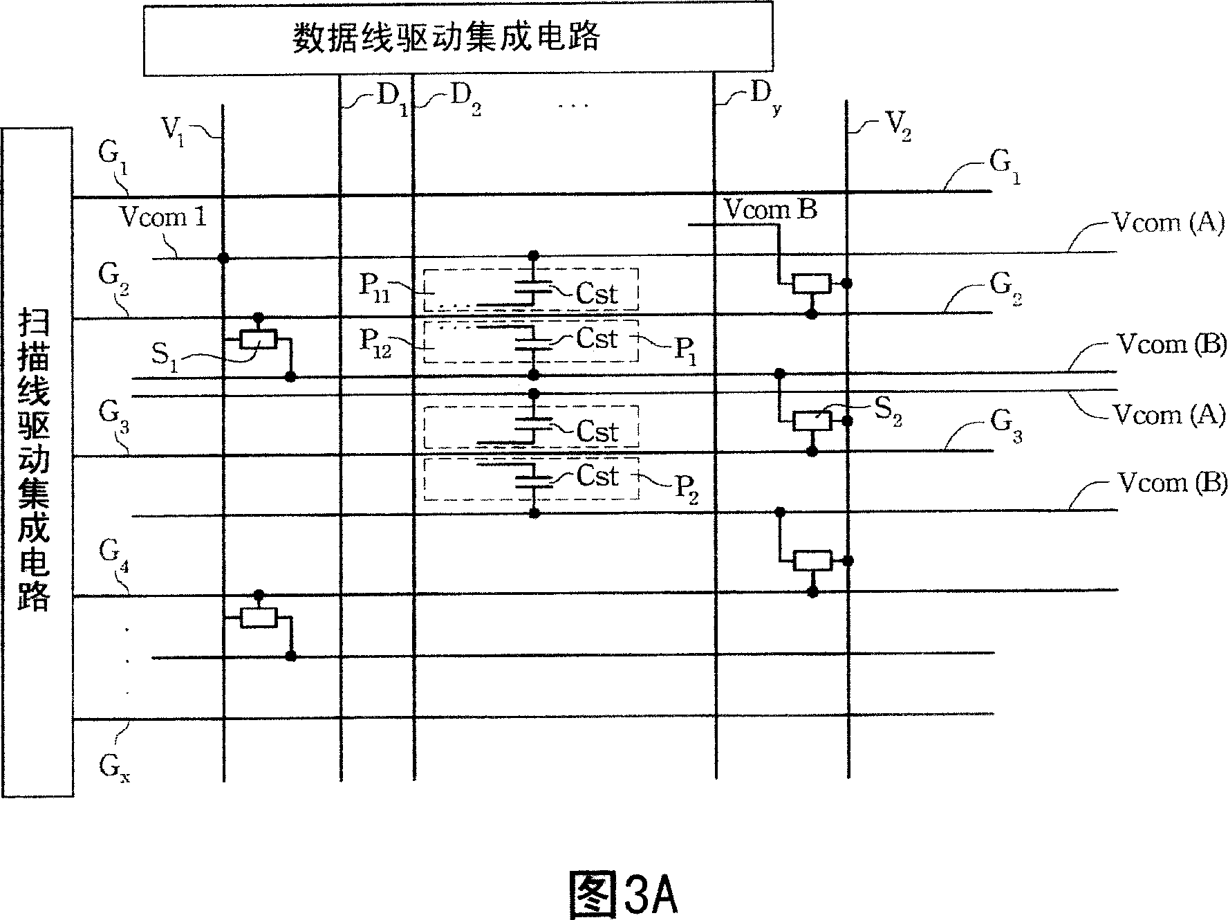
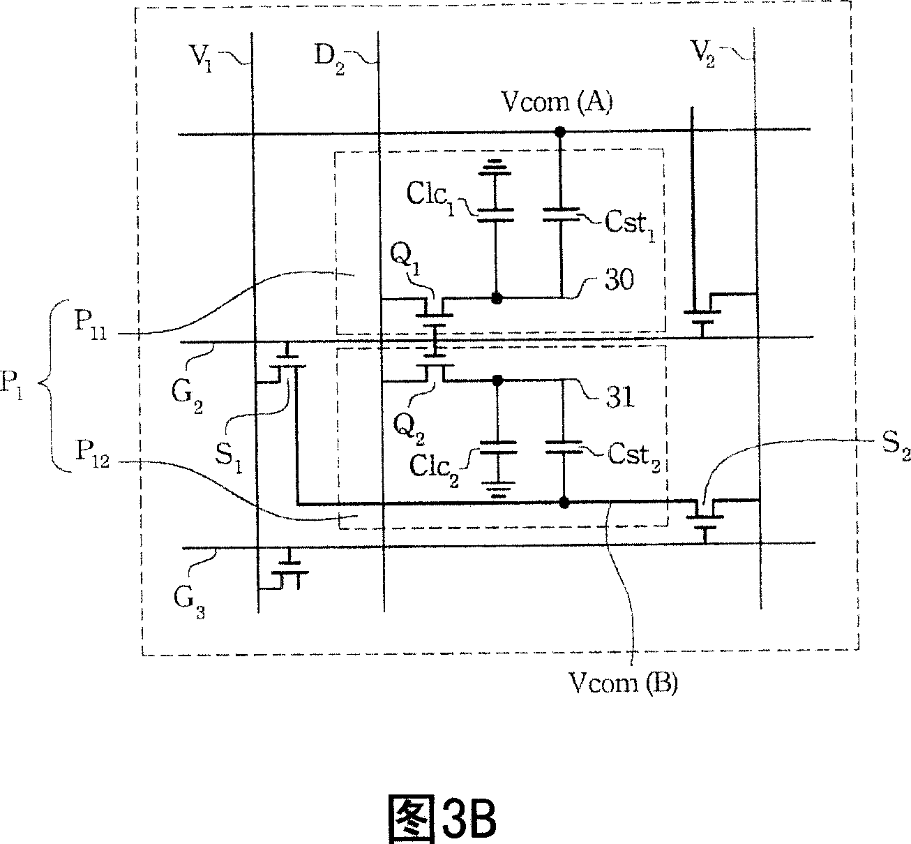
[0075] FIG. 3A is a schematic top view of a pixel unit according to the first embodiment of the present invention. As shown in the figure, the liquid crystal display of the present invention is composed of a plurality of data lines D coupled to the data line driver integrated circuit 1 、D 2 、D 3 ...D y , a plurality of scan lines G coupled to the scan line driver integrated circuit 1 , G 2 , G 3 ...G x and a plurality of common electrodes Vcom(A) and Vcom(B). Data line D 1 、D 2 、D 3 ...D y and scanline G 1 , G 2 , G 3 ...G x substantially perpendicular to each other, adjacent data lines and scan lines define a pixel unit P 1 , and each pixel unit includes two common electrodes Vcom(A) and Vcom(B) parallel to the scan lines. According to the first embodiment of the present invention, each pixel unit P 1 are separated into at least two sub-pixels P 11 and P 12 . at each pixel P 11 or P 12 includes a storage capacitor Cst composed of a pixel electrode and a ...


PUM


Abstract

A liquid crystal display is prepared for using multiple data line and scan line to define out pixel unit, forming each pixel unit by the first pixel and the second pixel, coupling the first shared electrode with at least one of multiple voltage source, electric-coupling the second shared electrode with two of multiple voltage source through the first and the second switching-over elements, and controlling the first and the second switching-over elements separately by their adjacent scan lines.

Description

technical field [0001] The present invention relates to a liquid crystal display, in particular to a pixel structure of a liquid crystal display. Background technique [0002] Liquid crystal displays have been widely used in various electronic products, such as electronic watches or calculators. In order to provide a wide viewing angle, Fujitsu (FujitSu) proposed a pixel division vertical alignment (Multi-Domain Vertical Alignment, MVA) technology in 1997. MVA technology can obtain a 160-degree viewing angle, and can also provide excellent performance with high contrast and fast response. However, the MVA technology has a great disadvantage, that is, when squinting, it will cause a color shift (color shift) phenomenon to the skin color of people, especially the skin color of Asians. [0003] FIG. 1 shows a graph showing the relationship between grayscale voltage and transmittance of liquid crystal molecules using MVA technology, wherein the horizontal axis represents the g...

Claims


Application Information

Patent Timeline
Patent Type & Authority Applications(China)
IPC IPC(8): G02F1/133G02F1/1362G09G3/36
Inventor 黄雪瑛赖明升江明峰
Owner AU OPTRONICS CORP
Why Eureka
Try Eureka