Cast-in-place concrete hollow-cavity shuttering member

A formwork component and cavity mold technology, which is applied to building components, building structures, floor slabs, etc., can solve the problems of inconvenient production, inconvenient assembly line production, and low production efficiency.

Inactive Publication Date: 2007-08-01
邱则有
View PDF2 Cites 0 Cited by
  • Summary
  • Abstract
  • Description
  • Claims
  • Application Information

AI Technical Summary

Problems solved by technology

However, this formwork component is inconvenient to manufacture, low in production efficiency, inconvenient for assembly line

Method used


Image

  • Cast-in-place concrete hollow-cavity shuttering member
  • Cast-in-place concrete hollow-cavity shuttering member
  • Cast-in-place concrete hollow-cavity shuttering member

Examples


Embodiment Construction

[0068] The present invention will be further described below in conjunction with the accompanying drawings and embodiments.

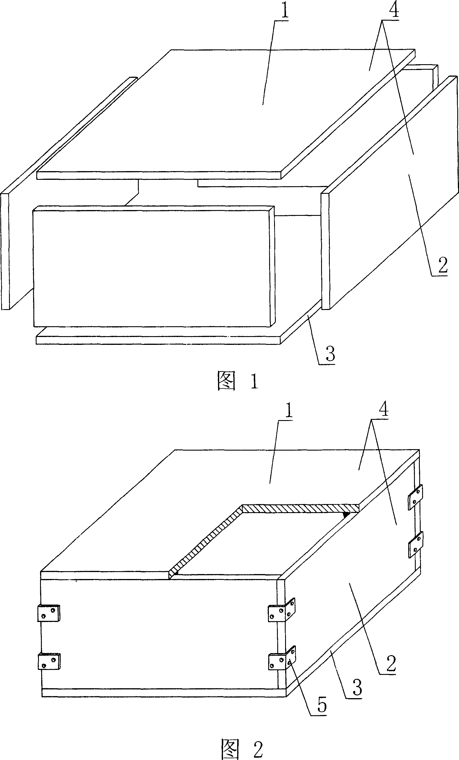
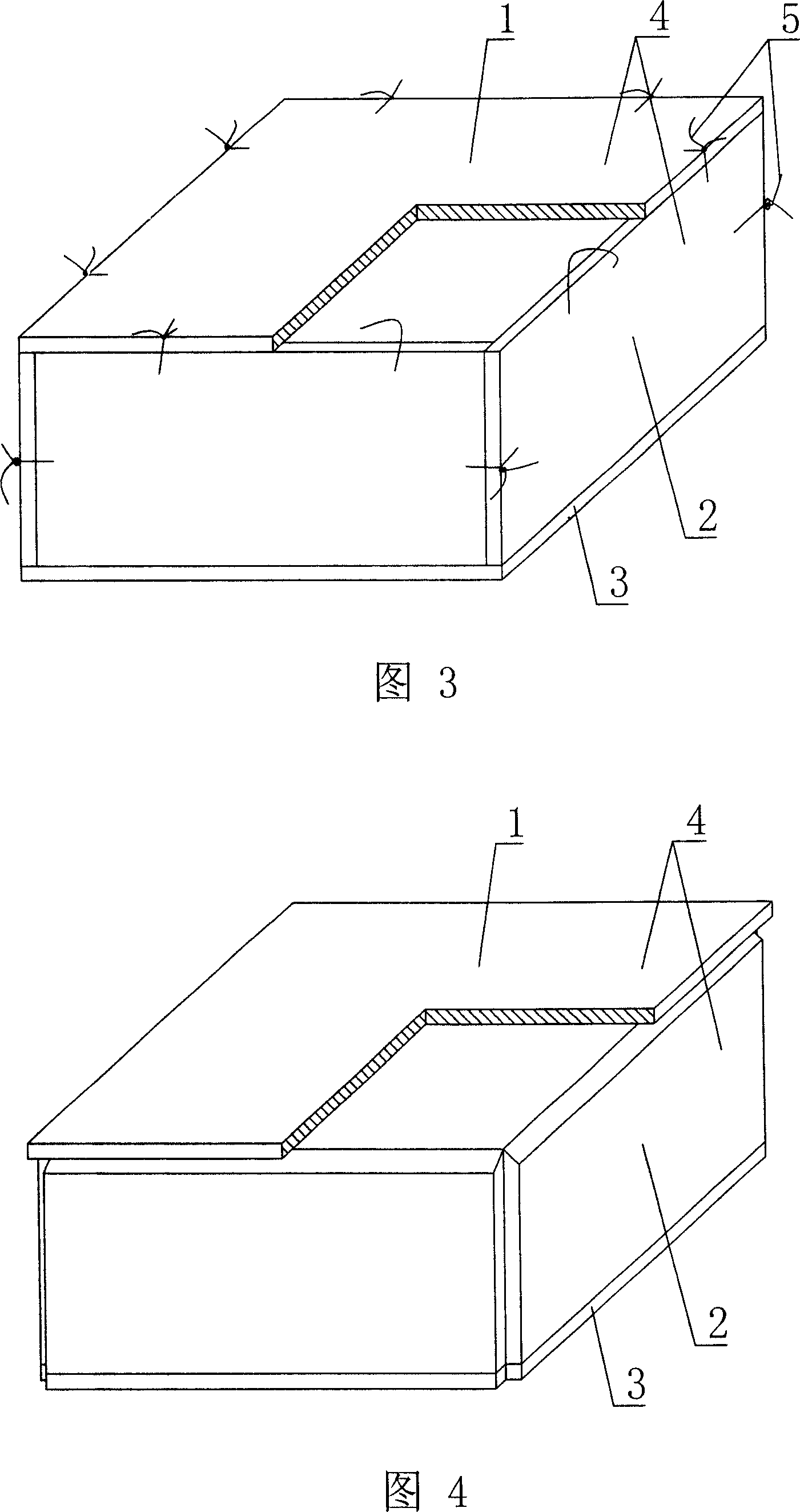
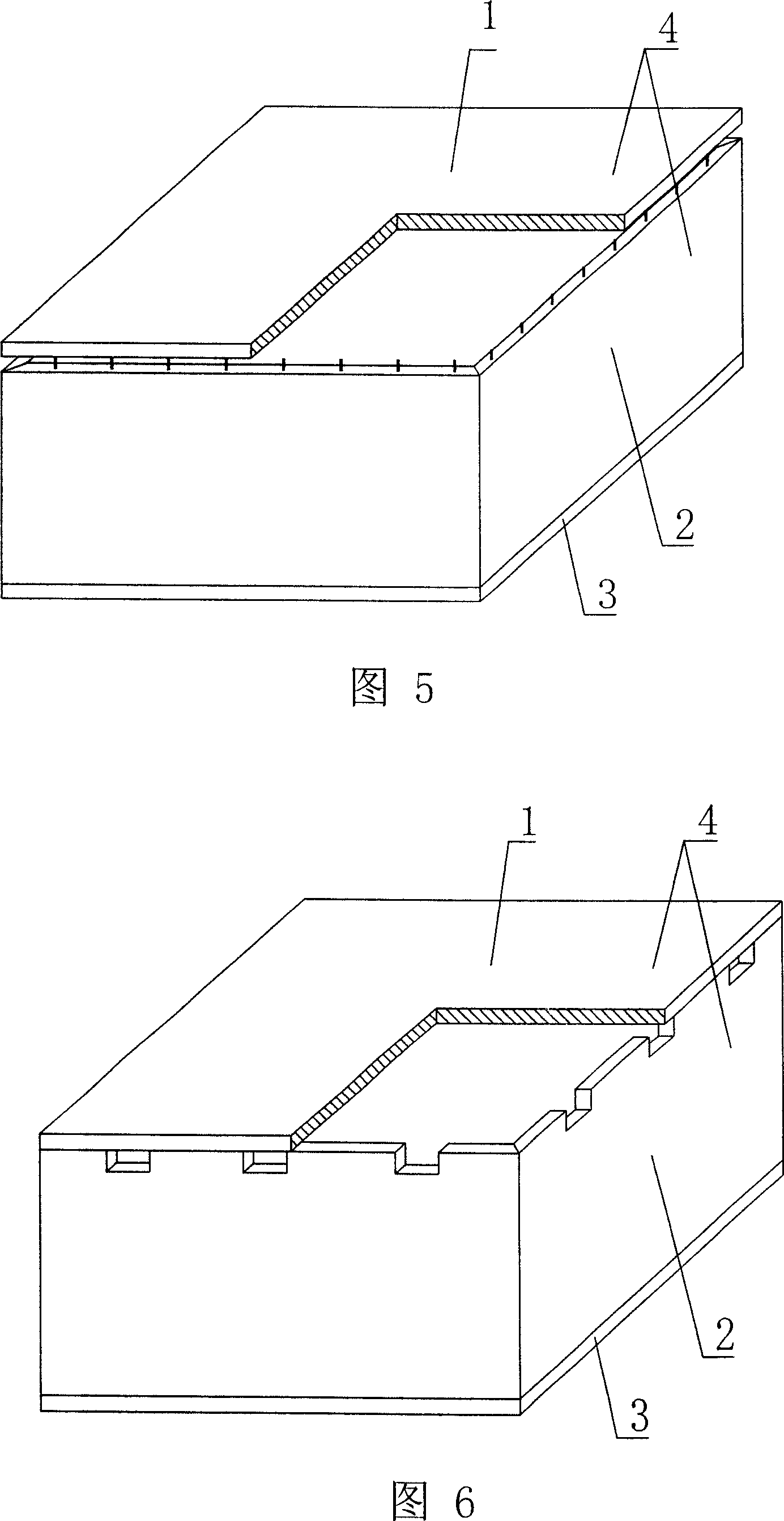
[0069] As shown in the accompanying drawings, the present invention includes an upper plate 1, surrounding side walls 2, and a lower plate 3, and the upper plate 1, surrounding side walls 2, and lower plate 3 form a closed cavity mold shell, and the upper plate 1 is an independent prefabricated The plate 4 is characterized in that the closed cavity formworks are all assembled from prefabricated components, at least two formworks are connected at intervals to form a group of formwork members, and there are formwork connectors 25 between the intervals. In each accompanying drawing, 1 is an upper plate, 2 is a surrounding side wall, 3 is a lower plate, and 4 is a prefabricated plate. In the following accompanying drawings, those with the same number have the same description. As shown in Figure 1, the upper plate 1, the surrounding side walls 2, and the lo...


PUM


Abstract

Disclosed is a hollow concrete shuttering member for concrete filling, which comprises an upper board (1), the peripheral side panels (2) and a lower board (3), wherein the upper board (1), the peripheral side panels (2) and the lower board (3) enclose a closed hollow shuttering, the upper board (1) is a separate prefabricated panel (4), characterized in that all of the hollow shuttering members are pasted from prefabricated panels (3), at least two of the shuttering members are arranged into one integrity, thereby forming clustered shuttering members, the invention can be applied to various cast-in-situ concrete building slabs, house roofings, walls, foundation bedplates and bridge structures, especially for hollow flat slabs.

Description

[0001] This application is a divisional application of an invention patent application with a filing date of December 9, 2003, an application number of 200310121939.5, and a title of “A Cavity Formwork Member for Concrete Filling”. (1) Technical field [0002] The invention relates to a cavity formwork component for concrete filling. (2) Background technology [0003] At present, the cast-in-place concrete hollow floor is a widely used floor structure, and the lightweight permanent tire mold filled in it includes hollow tubes and cavity formwork components. For example, the patent No. ZL99249798.1, which the applicant applied for on November 29, 1999, is a utility model patent named "fiber-reinforced thin-walled member for reinforced concrete filling", which discloses a thin-walled formwork member, including an upper plate, The surrounding side walls, the lower bottom, and the upper plate, the surrounding side walls and the lower bottom form a polyhedral cavity. Another exa...

Claims


Application Information

Patent Timeline
IPC IPC(8): E04B5/18E04B5/16E04B5/36E04C1/00E04C1/39
Inventor 邱则有
Owner 邱则有
Why Eureka
Try Eureka