Method and CT system for detecting and differentiating plaque in vessel structures of a patient

A vascular structure, plaque technology, applied in the field of computed tomography system, can solve problems such as limitations

Inactive Publication Date: 2007-08-08
SIEMENS AG
View PDF1 Cites 13 Cited by
  • Summary
  • Abstract
  • Description
  • Claims
  • Application Information

AI Technical Summary

Problems solved by technology

The distance a between the ray source and the observer is also subject to certain restrictions in medical diagnosis
Therefore, the source s is mostly reserved as the last degree of freedom, even though the relationship between source size and X-ray power is also strictly limited here

Method used


Image

  • Method and CT system for detecting and differentiating plaque in vessel structures of a patient
  • Method and CT system for detecting and differentiating plaque in vessel structures of a patient
  • Method and CT system for detecting and differentiating plaque in vessel structures of a patient

Examples


Embodiment Construction

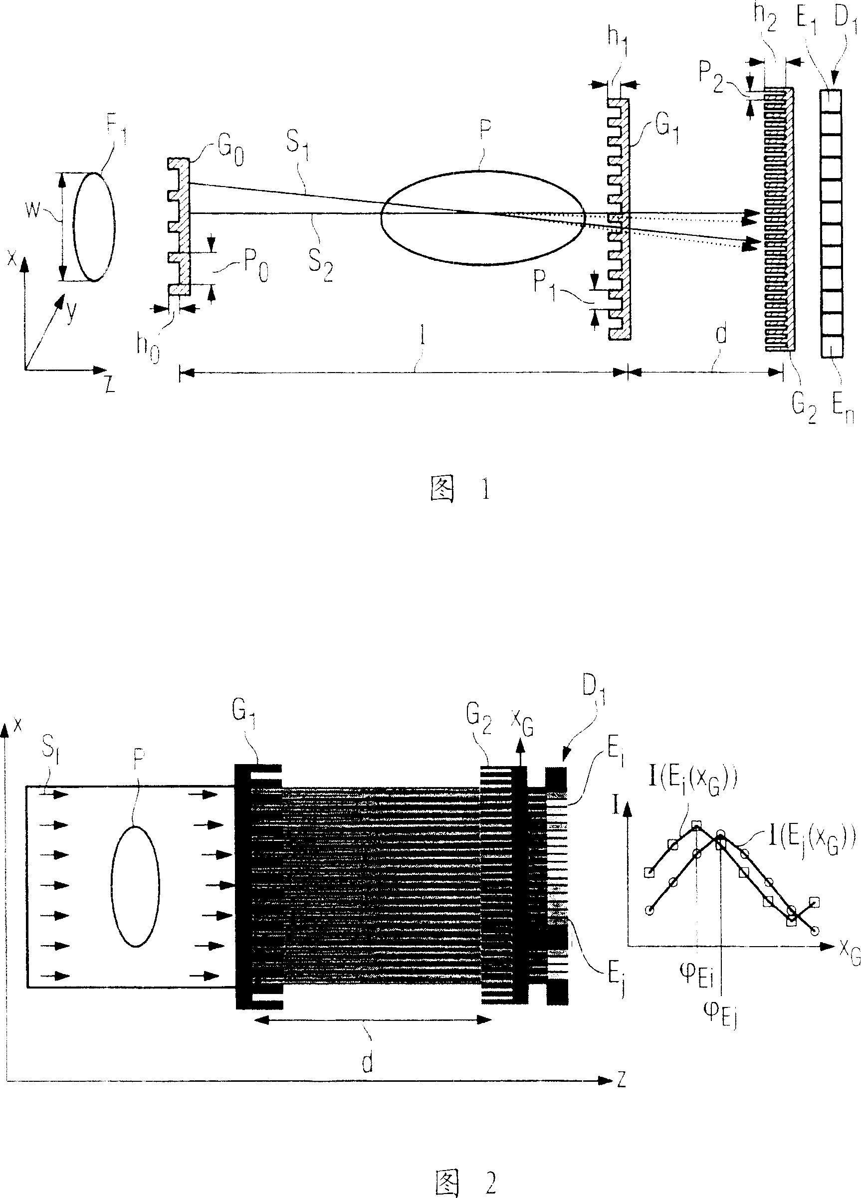
[0061] For a better understanding of phase-contrast measurements, a schematic diagram with a grating set G 0 to G 2 focus-detector system. In the first grating G 0 Previously had focus F 1 , and its maximum range is represented by w. first grating G 0 The period of the grating line is p 0 , the height of the grating bars is h 0 . Correspondingly, the grating G 1 and G 2 also has height h 1 and h 2 and period p 1 and p 2 . For phase measurement, the grating G 0 and G 1 The distance between 1 and the grating G 1 and G 2 The distance d between is set to a specific relationship. Here the following equation holds:

[0062] p 0 = p 2 × l d .

[0063] with detector element E 1 to E n detector D 1 with the last raster G 2 There is not much distance between them. Here the height h of the bars of the phase grating shou...


PUM


Abstract

A method and a CT system are disclosed for detecting and differentiating plaque in vessel structures of a patient. In at least one embodiment, a computed tomography system that is equipped with at least one focus detector system and, per focus detector system, with at least one transradiated x-ray/optical grating, is used to reconstruct the spatial distribution of the refractive index in the region of vessel structures of the patient from detected projection data. Further, at least one plaque form is highlighted in a pictorial display on the basis of a previously known value range of the refractive index for at least one plaque form.

Description

technical field [0001] The invention relates to a method for identifying and distinguishing plaques in a patient's vascular structure using a computed tomography system and a computed tomography system for performing the method. Background technique [0002] In general, methods for identifying and distinguishing plaques in the vascular structure of a patient by means of absorption computed tomography and the absorption CT systems used therefor are generally known. Most of these visualize vessel structures with the application of a contrast agent and determine the presence of plaque by looking more deeply at the edge regions of the visualized vessels with the help of absorption data. Attempts were also made to determine whether the firmness of the plaque was calcified or soft by means of absorption CT. Calcified plaque is usually not a health risk, while so-called soft plaque greatly increases the risk of myocardial infarction. However, when determining plaques, especially ...

Claims


Application Information

Patent Timeline
Patent Type & Authority Applications(China)
IPC IPC(8): A61B6/03G01N23/04G01N23/20G01N23/06H05G1/02H05G1/62G01T1/28G01T7/00G21K1/06G21K1/02
CPCA61B6/484A61B6/4291G01N2223/419G01N2223/612
Inventor 埃克哈德·亨普尔
Owner SIEMENS AG
Why Eureka
Try Eureka