

Cool-off heat sink of steady-state tokamak divertor
A tokamak and divertor technology, applied in cooling/ventilation/heating transformation, thermonuclear fusion reactors, nuclear reactors, etc., can solve the problem of discounting the cooling effect, difficulty in meeting the needs of the device, and inability to ensure the contact area between the cooling pipe and the base material, etc. problem, to achieve good cooling effect and reduce the effect of heat transfer distance
Inactive Publication Date: 2007-08-08
INST OF PLASMA PHYSICS CHINESE ACAD OF SCI
View PDF0 Cites 11 Cited by
- Summary
- Abstract
- Description
- Claims
- Application Information
AI Technical Summary
Problems solved by technology
No matter what structure is used to braze the cooling tube on the plate, the contact area between the cooling tube and the base material cannot be guaranteed, which greatly reduces the cooling effect and is difficult to meet the needs of the device
Method used
View moreImage
Smart ImageViewing Examples

Examples
Embodiment Construction
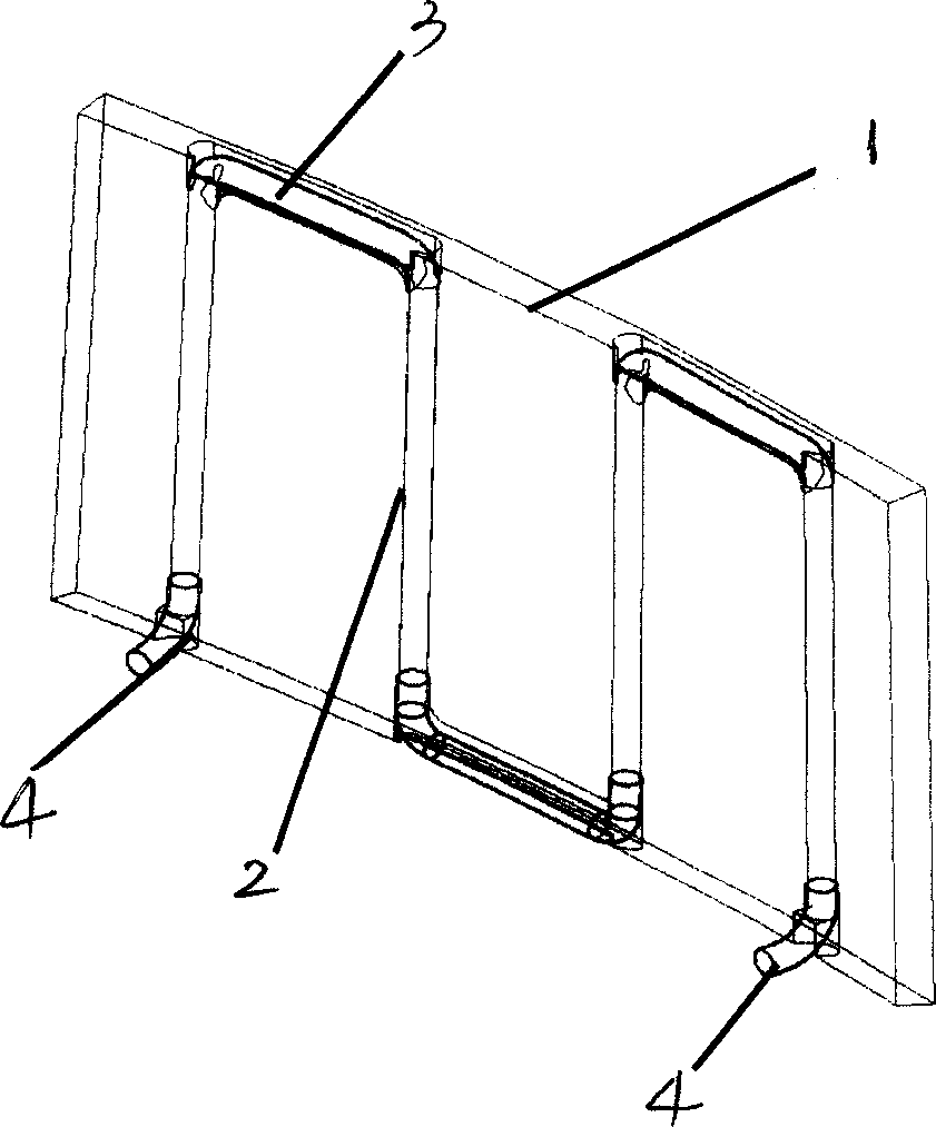
[0010] As shown in the figure, the present invention includes a copper alloy heat sink plate 1, a cooling channel 2, a connecting pipe 3 and a stainless steel outlet pipe 4, wherein the aperture of the cooling channel 2 and the density distributed on the heat sink plate can be adjusted as required.
[0011] The present invention is limited by the deep hole technology, and is only suitable for cooling channel holes with a depth of not more than 1.8 meters and a hole diameter of 3-36mm.
Login to View More PUM
 Abstract
The invention is a steady state Tokamak diverter cooling heat sink, including heat sink plate. Its characteristic is there are a number of cooling channels in the heat sink plate. In the lateral of the heat sink plate, the adjacent cooling channels are connected by pipes to form a series circuit. For the steady long - pulsed operated Tokamak device, the energy deposition on the diverter will be great. So the diverter must have a strong initiative cooling system. The invention can meet those requirements.
Description
technical field [0001] The invention belongs to a cooling device in a magnetic confinement nuclear fusion device, in particular to a steady-state tokamak divertor cooling device. Background technique [0002] In the magnetic confinement nuclear fusion device, the energy for heating the plasma and the energy generated by fusion will be mainly deposited on the divertor, and the power density generated by these energies on the divertor will reach 20MW / m 2 above. Such a large power density, if there is no effective energy transmission speed to remove the energy as fast as possible, will quickly cause the temperature on the divertor to rise to a height that the material cannot withstand. Most of the divertor tokamaks operated in the past and currently are discharges with plasma pulse lengths ranging from a few seconds to more than ten seconds. Although the power density on the divertor is high, the total energy is not large. The temperature rise caused by the filter will not be...
Claims
Login to View More Application Information
Patent Timeline
 IPC IPC(8): G21B1/11G21B1/13H05K7/20
CPCY02E30/128Y02E30/122Y02E30/10
Inventor姚达毛
OwnerINST OF PLASMA PHYSICS CHINESE ACAD OF SCI