Analog external cavity laser

A laser and laser cavity technology, applied in the field of laser light sources, can solve problems such as high cost and complexity

Inactive Publication Date: 2007-08-08
K2 OPTRONICS
View PDF5 Cites 4 Cited by
  • Summary
  • Abstract
  • Description
  • Claims
  • Application Information

AI Technical Summary

Problems solved by technology

However, this approach has had very limited commercial success due to its high cost and complexity (see, for example, "Dependence of Semiconductor Laser Intermodulation Distortion on Fiber Length and its Distortion by Optical Injection Locking" by H. Sung et al. (Dependence of Semiconductor LaserIntermodulation Distortion on Fiber Length and its Reduction by Optical InjectionLocking)", Conference Proceedings, Paper WE2 10, pp. 186-200)

Method used


Image

  • Analog external cavity laser
  • Analog external cavity laser
  • Analog external cavity laser

Examples


Embodiment Construction

[0045] After considering the following description, it will be apparent to those skilled in the art that the teachings of the present invention may be readily applied to the design, fabrication, packaging, and / or use of external cavity lasers (ECLs), especially analog ECLs.

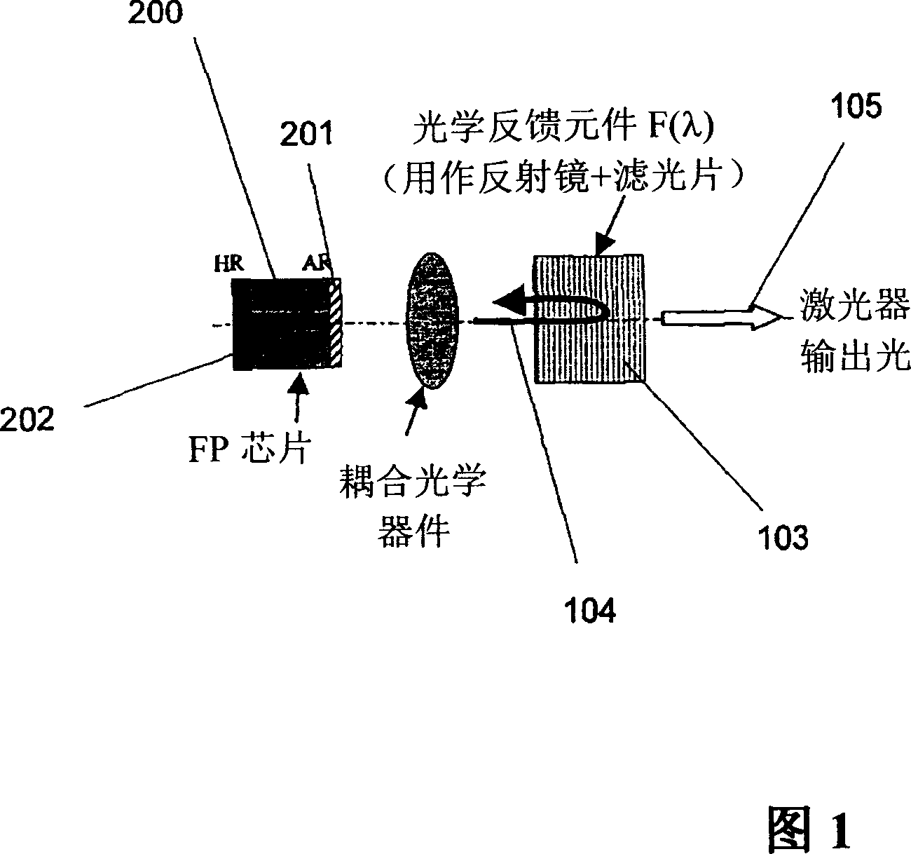
[0046] The technology described herein relates to analog external cavity lasers, including techniques for designing, packaging, and improving the performance of ECLs for use in analog and CATV fiber optic communication systems. This field of application is merely an example and not limiting, as the systems, techniques, processes, devices, and materials described herein may also be applied in other fields. The simulated ECL described in this paper is a directly modulated laser source, which has obvious advantages over other devices and systems for simulating optical transmission. These advantages include higher performance in terms of distortion and chirp (for example), lower cost, and improved design marg...


PUM


Abstract

The present invention relates to the analog external cavity lasers (ECLs) including designs, materials, methods of manufacturing and methods of use for such ECLs and packages for such ECLS. Numerous criteria are presented that lead to improved cost / performance for ECLs and for systems incorporating such ECLs.

Description

[0001] Related Application Cross Reference [0002] This application is filed under Provisional Patent Application No. 60 / 558,927, filed April 2, 2004, and filed April 16, 2004, asserting one or more of 35 U.S.C. §119, §120, §365 Priority to Provisional Patent Application No. 60 / 562,762, filed December 23, 2004, and Provisional Patent Application No. 60 / 638,679, filed December 23, 2004. The entire contents of all said provisional patent applications are hereby incorporated by reference for all purposes. technical field [0003] The present invention relates generally to the field of laser light sources, and more particularly to external cavity laser light sources. Background technique [0004] Directly modulated distributed feedback (DFB) laser diodes are widely used in many applications, including multi-channel transmission of analog modulated signals typically used in analog broadcast, digital simulcast and narrowband broadcast (QAM format) in cable television (CATV) and...

Claims


Application Information

Patent Timeline
Patent Type & Authority Applications(China)
IPC IPC(8): H01S5/14H01S5/00H01S3/08H01S3/00H04B10/155H03F1/32H01S5/065
Inventor 弗拉迪米尔·库珀尔施米特弗兰斯·库斯纳迪约翰·梅杰萨贝尔·西亚拉
Owner K2 OPTRONICS
Why Eureka
Try Eureka