A milling tool, a cutting insert for milling tool as well as a solid milling tool

A blade and milling cutter technology, which is applied in the field of milling cutters, blades for milling cutters and integral blades, can solve the problems of limiting the service life of milling cutters and adverse effects on cutting edge strength, and achieve improved chip removal speed and high chip removal speed effect

Inactive Publication Date: 2007-08-08
SANDVIK INTELLECTUAL PROPERTY AB
View PDF0 Cites 12 Cited by
  • Summary
  • Abstract
  • Description
  • Claims
  • Application Information

AI Technical Summary

Problems solved by technology

However, both solutions adversely affect the strength of the cutting edge, thus limiting the service life of the milling cutter

Method used


Image

  • A milling tool, a cutting insert for milling tool as well as a solid milling tool
  • A milling tool, a cutting insert for milling tool as well as a solid milling tool
  • A milling tool, a cutting insert for milling tool as well as a solid milling tool

Examples


Embodiment Construction

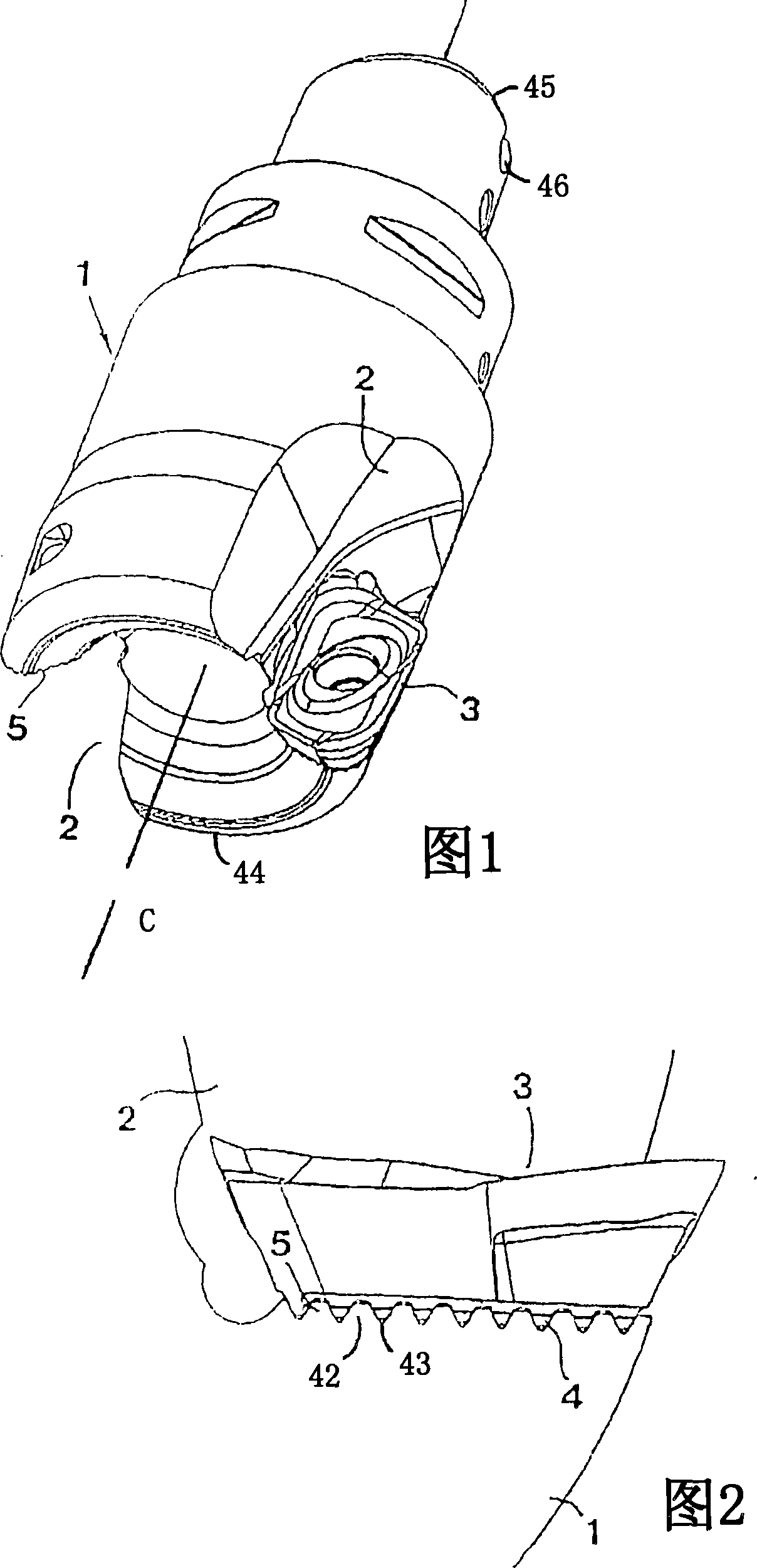
[0024] In FIG. 1 , a milling cutter according to a preferred embodiment of the invention is shown, comprising a body 1 having a rotationally symmetrical basic shape, the body 1 having a front end surface 44 and a rear end surface 45 comprising a The means attached to the drive spindle, ie the recessed portion 46. The body can rotate around the geometric central axis C. Two chip channels 2 are formed on the envelope surface of the body 1 . In one of the chip channels, a milling insert 3 according to an embodiment of the invention is installed. In FIG. 2 , it can be seen that the blade 3 has at the bottom side at least one connection surface 4 , of the type comprising a plurality of parallel ridges spaced apart via grooves, the ridges having a conical shape in cross-section. This connection surface is intended to cooperate with a similar connection surface 5 provided by the ridge, which is arranged in the body 1 and forms an insert seat 5 in the chip channel 2 . It should be ...


PUM


Abstract

The invention relates to a milling tool intended for chip-removing machining, comprising a basic body rotatable around a geometrical centre axis and a plurality of peripherically spaced-apart, detachable cutting inserts, which separately are securable in insert pockets adjacent to chip channels formed in the basic body, the individual cutting insert having at least one edge (19) formed between a chip surface on the top side of the cutting insert and a clearance surface along the periphery side of the cutting insert, the tool geometry being markedly positive so far that the individual insert pocket is arranged to secure the individual cutting insert in a position in which the chip surface is inclined in relation to the centre axis while forming a positive angle of inclination. Characteristic of the invention is the combination that the angle of inclination between the chip surface (17b) and the centre axis is within the range of 25-28 DEG , that the cutting edge (19) cross section- wise has an arc-shape having a radius of curvature (ER) within the range of 5-20 mu m, that the clearance surface of the cutting insert is formed with a clearance bevel (18a), which extends from the cutting edge (19) in the direction of the bottom side of the cutting insert and transforms into a main clearance portion (18b), that the clearance angle (Gamma) of the clearance bevel (18a) is larger than 0 DEG , but smaller than 3 DEG , that the clearance angle (Omega) of the main clearance portion (18b) is larger than the clearance angle (Gamma) of the clearance bevel (18a), that the extension of the clearance bevel (18a) from the cutting edge (19) to the main clearance portion (18b) is within the range of 0,05-0,30 mm, that the chip surface is formed with a reinforcement bevel (17a), which extends from the cutting edge (19) in the direction of the centre of the cutting insert and transforms into a main chip portion (17b).

Description

technical field [0001] In a first aspect, the invention relates to a milling cutter designed for chip removal machining, comprising a body rotatable about a geometric central axis and a plurality of removable inserts spaced apart on the periphery, said inserts being respectively fixed In the insert seat adjacent to the chip channel formed in the body, each insert has at least one cutting edge formed between the chip surface on the top side of the insert and the clearance surface along the peripheral side of the insert, the cutter geometry being clearly positive (positive) so that each insert seat is arranged to secure each insert in a position where the chip surface is inclined with respect to the central axis while forming a positive inclination angle. [0002] In a second aspect, the invention also relates to an insert for a milling cutter. [0003] In a third aspect, the invention relates to a solid milling cutter. Background technique [0004] In the field of stock rem...

Claims


Application Information

Patent Timeline
Patent Type & Authority Applications(China)
IPC IPC(8): B23C5/20B23C5/18B23CB23C5/10
CPCY10T407/235Y10T407/1946Y10T407/1938B23C5/207B23C5/10B23C2200/125B23C2210/084B23C2210/126B23C2210/0407B23C5/109Y10T407/23B23C2200/165Y10T407/245Y10T407/1948B23C2210/0442B23C5/202
Inventor 英厄·斯韦宁松米卡埃尔·伦德布拉德扬·约翰松芒努斯·阿斯特伦戴维·欧隆德
Owner SANDVIK INTELLECTUAL PROPERTY AB
Why Eureka
Try Eureka