High frequency heating device

A high-frequency heating device and high-frequency technology are applied in the direction of induction heating to achieve the effect of reducing manufacturing costs

Inactive Publication Date: 2007-08-15
PANASONIC CORP
View PDF1 Cites 4 Cited by
  • Summary
  • Abstract
  • Description
  • Claims
  • Application Information

AI Technical Summary

Problems solved by technology

[0004] The present invention aims to solve the above-mentioned problems in the prior art, and its purpose is to safely discharge the dripping water from the heating chamber without complicating the structure of the device, so as to prevent the water from overflowing outside the body and causing product quality. The drop phenomenon, product misuse and electric shock accidents caused by water seepage can also be prevented

Method used


Image

  • High frequency heating device
  • High frequency heating device
  • High frequency heating device

Examples


Embodiment Construction

[0021] An embodiment of the present invention will be described in detail below with reference to the accompanying drawings. It should be pointed out that this embodiment does not limit the scope of the present invention.

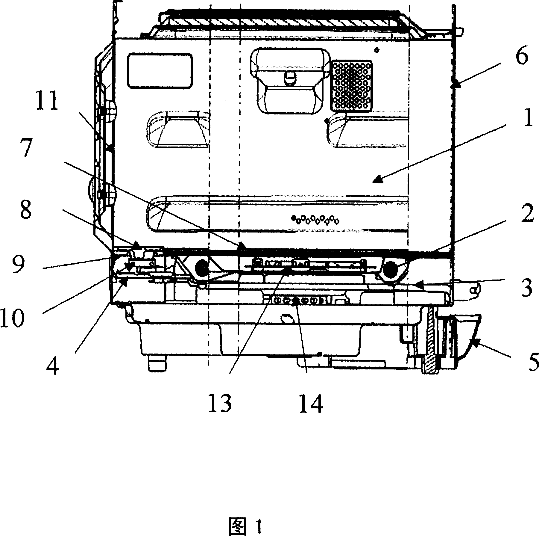
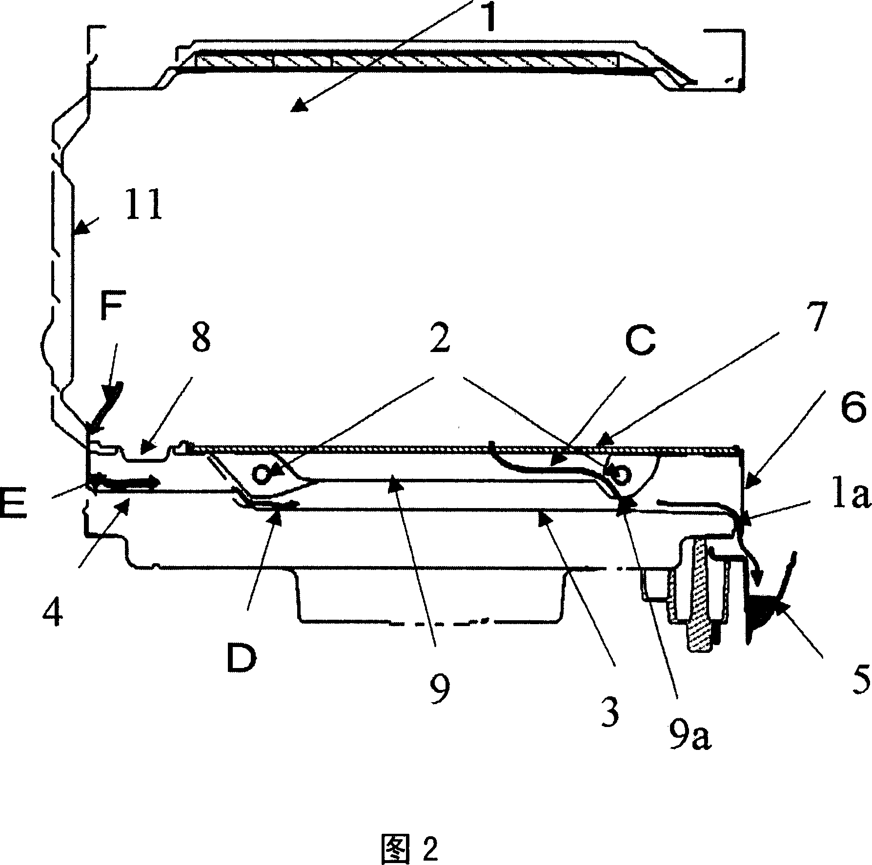
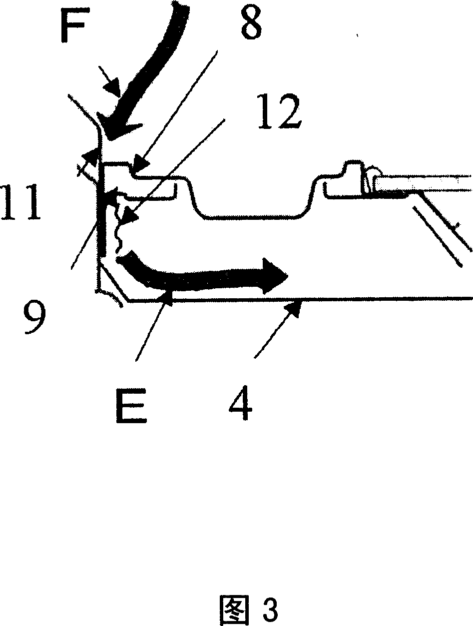
[0022] Fig. 1 is a side sectional view of the high-frequency heating device in Embodiment 1 of the present invention, Fig. 2 is a side sectional view for expressing the drainage water flow therein, Fig. 3 is a partial enlarged sectional view of Fig. 2, Fig. 4 And Fig. 5 is a perspective view for showing the drainage water flow.

[0023] As shown in Fig. 1, be provided with in the heating chamber 1: be used to place the ceramic stage 7 of object to be heated; Constitute the heater 2 of the electrothermal device that is heated to object to be heated; The rotating waveguide 13 of the high frequency generating device. In addition, the above-mentioned heating chamber 1 is combined by riveting the evaporating dish 8, the rear wall 11 of the heating chamber and ...


PUM


Abstract

The invention provides a high-frequency heating device that prevents dripping water generated by condensation from entering the mechanical chamber through a low-cost and simple structure, comprising: a heating chamber (1) for accommodating objects to be heated; A high-frequency generating device for heating; an electric heating device (2) arranged at the lower part of the heating chamber to heat the object to be heated; and a steam generating device (8) for generating steam in the heating chamber. Below the heating chamber is a heater heat reflection plate (3) for receiving dripping water from the heating chamber, and a detachable water receiving tray (5) is provided on the front surface of the body, and the heater heat reflection plate guides the dripping water into the catchment tray located on the front surface of the body. In this way, without complicating the structure of the device, it is possible to prevent the residual water of water vapor due to condensation in the heating chamber from overflowing outside the body, avoiding the degradation of product quality, product misoperation and electric shock caused by water seepage. Accidents are also reliably prevented.

Description

technical field [0001] The present invention relates to a high-frequency heating device having the function of heating an object to be heated after combining high-frequency heating and steam heating. Safety measures for spilled water. Background technique [0002] Among the existing high-frequency heating devices, some adopt the structures shown in Fig. 6 to Fig. 8 . That is, the water supplied to the evaporating pan 8 of the heating chamber 1 is heated by an evaporating pan heater (not shown in the figure) to become water vapor. However, the air containing such water vapor will condense in the heating chamber 1, forming the heating chamber residual water F (see Figure 7) in the heating chamber 1, and from the joint between the evaporating dish 8 and the heating chamber 1 Drip water outside the heating chamber 1. The bottom of the evaporating dish 8 is provided with a water-receiving isolation part 4, which allows the dripping water to stay therein. In this way, the phen...

Claims


Application Information

Patent Timeline
Patent Type & Authority Applications(China)
IPC IPC(8): H05B6/02
Inventor 神谷利文
Owner PANASONIC CORP
Why Eureka
Try Eureka