Control circuit and method for manipulating a power tool

a control circuit and power tool technology, applied in the direction of portable power-driven tools, dynamo-electric converter control, instruments, etc., can solve the problems of harming users, user not knowing the remaining battery capacity of the battery pack, and incorrect so as to achieve the effect of accurate display of the remaining battery capacity

Active Publication Date: 2011-12-15
CHERVON HK LTD WANCHAI
View PDF8 Cites 14 Cited by
  • Summary
  • Abstract
  • Description
  • Claims
  • Application Information

AI Technical Summary

Benefits of technology

[0008]The control circuit considers the variation of the resistance of the discharge loop of the battery due to the increase of the temperature resulting from the battery discharge and the voltage of the discharge loop of the battery. This allows for the measured voltage of the battery pack to be closer to the real voltage of the battery pack and results in the display of the remaining battery capacity to be more accurate.
[0010]The method for controlling may also include detecting and judging the various parameters of the battery before the motor is put in operation which could avoid an impact on the motor caused by an abnormal status of the battery and avoid an emergency. The method may also include calculating and displaying the remaining battery capacity after the motor starts operating, and repeating the detecting and judging of the various parameters of the battery and the calculating and displaying of the remaining battery capacity which would monitor the operational status of the battery in real time and make the discharge of the battery safer. The detecting and displaying of the remaining battery capacity in real time also makes the display of the remaining battery capacity more accurate.

Problems solved by technology

Because of the variance, the measured voltage does not always accurately reflect the energy of the battery for the motor and results in an incorrect display of the remaining battery capacity.
As a result, when the power tool starts operating, the user does not know the remaining battery capacity of the battery pack.
Because the parameters of the battery pack are not monitored during use, if the battery pack is over-current or over-temperature, the power tool will not create an alert or stop operating, which could harm a user.

Method used


Image

  • Control circuit and method for manipulating a power tool
  • Control circuit and method for manipulating a power tool
  • Control circuit and method for manipulating a power tool

Examples


Embodiment Construction

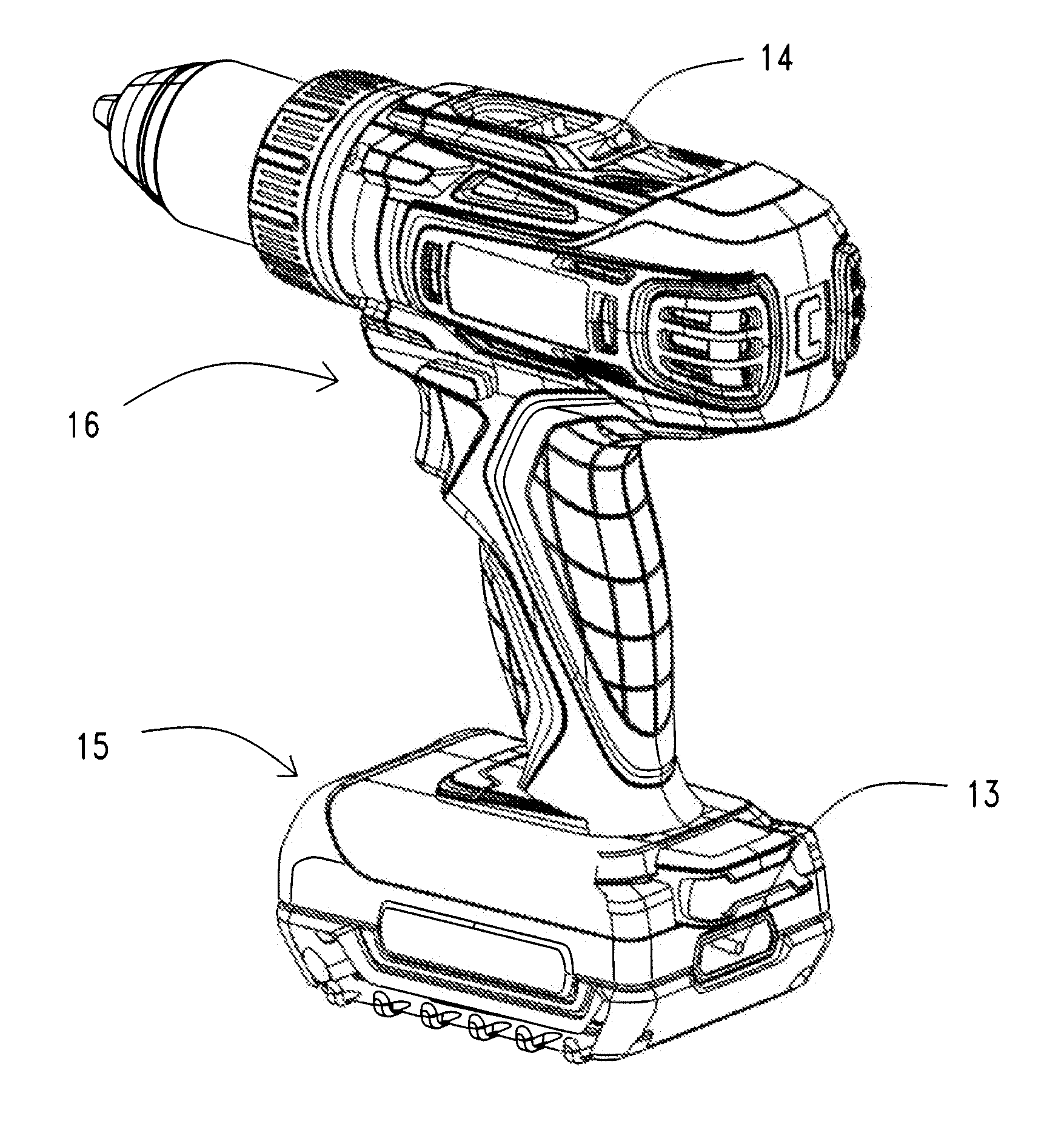
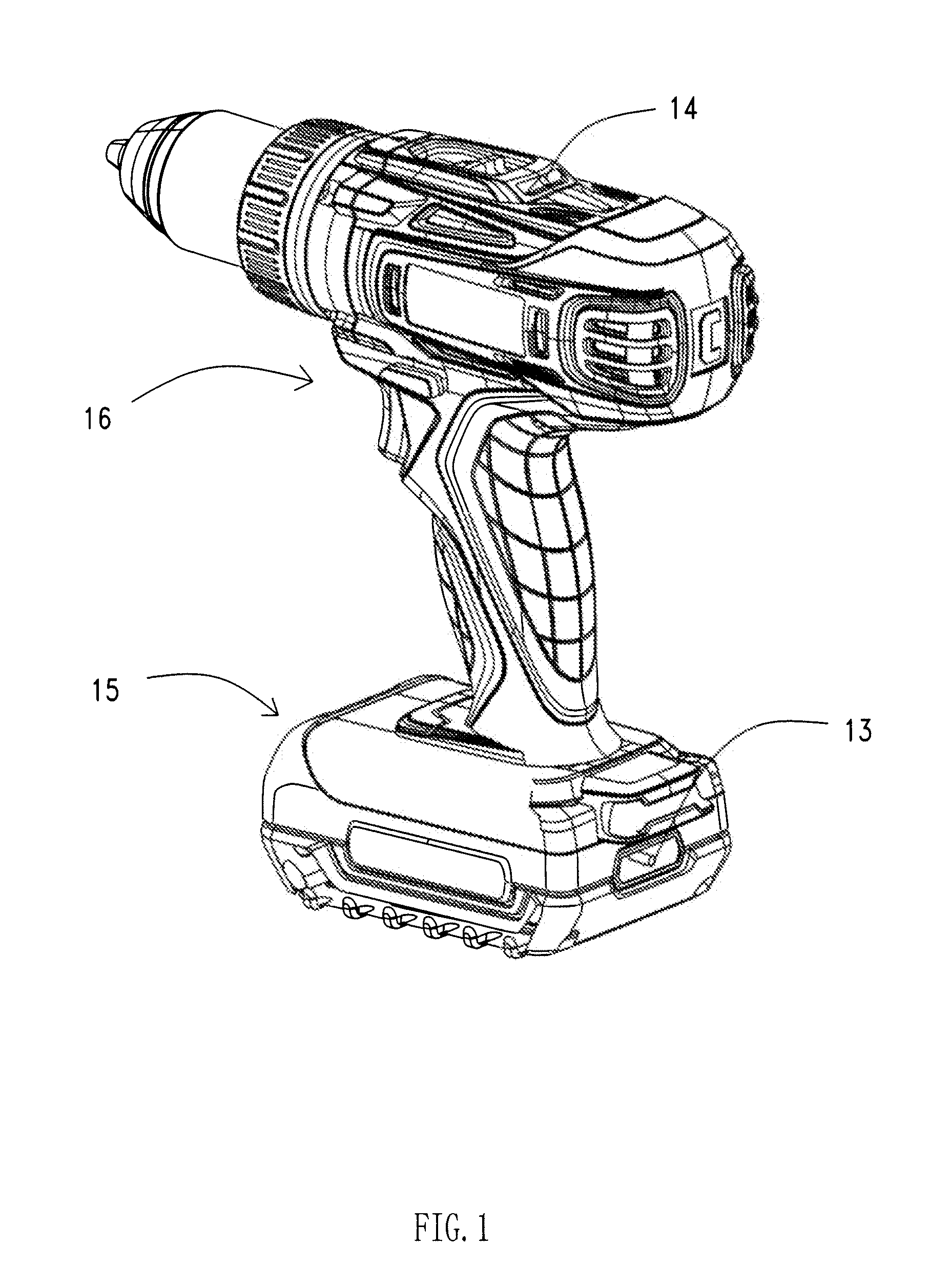
[0020]The invention will now be explained with reference to the drawings and examples below. In ordinary operationing situations, the DC power tool comprises a switch, a battery pack containing multiple rechargeable batteries, and a motor installed in the housing of the tool. Battery capacity displaying devices, for displaying the status of the battery pack capacity, are installed on the body of the tool and the battery pack. Using electrical drills as an example, as shown in FIG. 1, both the body 16 of the electrical drill and the battery pack 15 have battery capacity indicators. A body battery capacity indicator 14 is installed on the top of the body 16 of the tool, and a battery pack capacity indicator 13 is installed at the rear side of the battery pack 15. The battery pack capacity indicator 13 and the body battery capacity indicator 14 are preferably bicolor LED lamps in red and green which are capable of displaying three colors. The lamps display red when the red LED lamp is ...


PUM


Abstract

The present application discloses a control circuit for a power tool and a method for manipulating the power tool. The control circuit has a detection circuit for battery packs, a calculating control circuit, a battery capacity indicating circuit for indicating the calculation result of the battery capacity, and a current measure and calculating circuit for measuring the current flowing through motors. The calculation result further includes the voltages consumed by the battery pack internally and the discharge loop. The method for manipulating the power tool includes pressing the switch to electrically connect the motor and the battery pack, measuring the parameters of the battery pack and allowing the motor to operate or not according the measured parameters. Further, after the motor is in operation, the battery capacity is calculated and the results are displayed.

Description

CROSS-REFERENCE TO RELATED APPLICATIONS[0001]This application claims priority to CN 201010199754.6, filed Jun. 9, 2010, and CN 201010204598.8, filed Jun. 11, 2010, which are hereby incorporated by reference.FEDERALLY SPONSORED RESEARCH OR DEVELOPMENT[0002]Not Applicable.TECHNICAL FIELD[0003]The present application relates to a control circuit for a power tool and a method for manipulating the power tool.BACKGROUND OF THE INVENTION[0004]Generally, a power tool having a battery pack has the ability to display the remaining battery capacity. In ordinary situations, the displayed remaining battery capacity is obtained by directly measuring the voltage between the two ends of the battery. When the battery is discharging, the temperature of the battery increases and the inner resistance varies according to the temperature. Because of the variance, the measured voltage does not always accurately reflect the energy of the battery for the motor and results in an incorrect display of the rema...

Claims


Application Information

Patent Timeline
Patent Type & Authority Applications(United States)
IPC IPC(8): H02P6/08
CPCG01R31/3682G01R31/3646Y02E60/10G01R31/371B25F5/02H01M10/48H01M10/488
Inventor YANG, DEZHONGGENG, ZHENG
Owner CHERVON HK LTD WANCHAI
Why Eureka
Try Eureka