Capacitive touch circuit

a capacitive touch and circuit technology, applied in the field can solve the problems of inflexible adjustment of the impedance of the relaxation oscillator, increased fabrication costs, and complicated architecture of the touch sensing circuit, so as to effectively eliminate unstable signal transition, reduce fabrication costs, and simplify the effect of capacitive touch circuits

Inactive Publication Date: 2011-01-20
SONIX TECH
View PDF10 Cites 13 Cited by
  • Summary
  • Abstract
  • Description
  • Claims
  • Application Information

AI Technical Summary

Benefits of technology

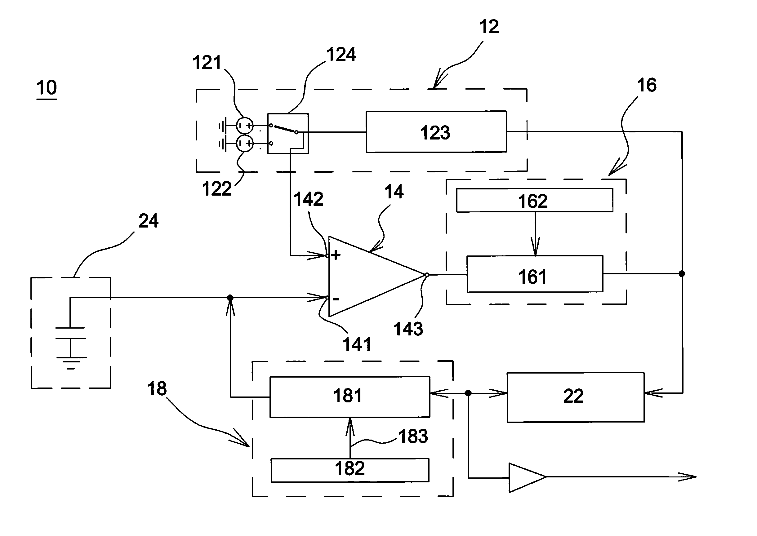
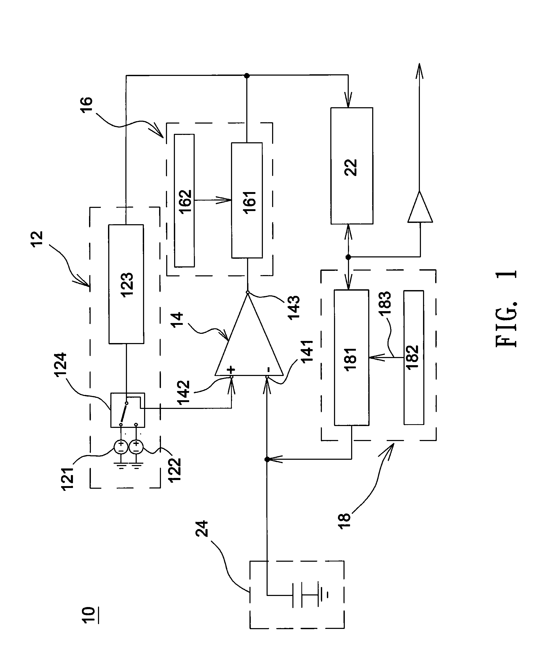
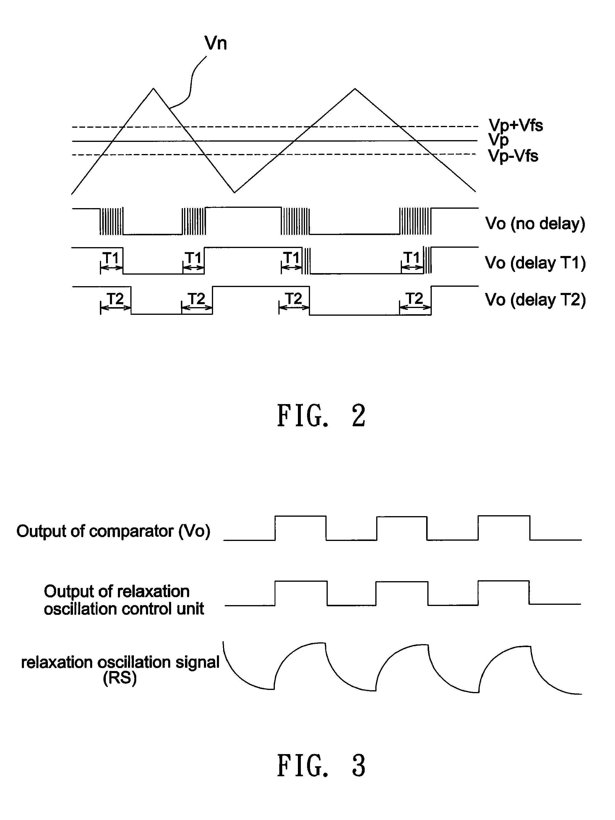
[0008]According to the above embodiment, charge and discharge operations are performed only as a single comparator and two voltage sources are provided. Hence, the architecture of the capacitive touch circuit is considerably simplified. Further, since the resistance adjusting unit is allowed to adjust the RC constant and hence the impedance of the relaxation oscillation control unit, accurate capacitive touch sensing is always achieved under different environmental conditions and touch sensing applications, without the need of an external compensation device. Hence, the fabrication costs can be further reduced. Besides, through the design of the delay unit, the comparator may output signals with hysteresis to effectively eliminate unstable signal transition.

Problems solved by technology

Hence, the fabrication costs are increased and the adjustment to the impedance of the relaxation oscillator is inflexible.
Further, in the conventional design, two comparators are used to perform charge and discharge operations for the relaxation oscillator to result in a complicated architecture of a touch sensing circuit.

Method used


Image

  • Capacitive touch circuit
  • Capacitive touch circuit
  • Capacitive touch circuit

Examples


Embodiment Construction

[0017]In the following detailed description of the preferred embodiments, reference is made to the accompanying drawings which form a part hereof, and in which are shown by way of illustration specific embodiments in which the invention may be practiced. In this regard, directional terminology, such as “top,”“bottom,”“front,”“back,” etc., is used with reference to the orientation of the Figure(s) being described. The components of the present invention can be positioned in a number of different orientations. As such, the directional terminology is used for purposes of illustration and is in no way limiting. On the other hand, the drawings are only schematic and the sizes of components may be exaggerated for clarity. It is to be understood that other embodiments may be utilized and structural changes may be made without departing from the scope of the present invention. Also, it is to be understood that the phraseology and terminology used herein are for the purpose of description an...


PUM


Abstract

A capacitive touch circuit includes a single comparator, a reference voltage control unit, a resistance adjusting unit, a delay unit, and a relaxation oscillation control unit. The comparator has a first input terminal, a second input terminal, and an output terminal. The reference voltage control unit is electrically connected to the second input terminal and includes a high level voltage source, a low level voltage source, and a voltage switching controller. The voltage switching controller electrically connects either the high level voltage source or the low level voltage source to the second input terminal of the single comparator according to an output signal of the single comparator. The relaxation oscillation control unit is electrically connected to the resistance adjusting unit, the delay unit, and the reference voltage control unit. The relaxation oscillation control unit outputs a relaxation oscillation signal, and the frequency of the relaxation oscillation signal varies according to the resistance set by the resistance adjusting unit.

Description

CROSS REFERENCE TO RELATED APPLICATION[0001]This application claims priority of application No. 098123675 filed on Jul. 14, 2009 in Taiwan R.O.C under 35 U.S.C. §119; the entire contents of which are hereby incorporated by reference.BACKGROUND OF THE INVENTION[0002]1. Field of the Invention[0003]The invention relates to a capacitive touch circuit.[0004]2. Description of the Related Art[0005]Nowadays, a capacitance sensor is widely used in different touch sensing devices such as a capacitive touch key, a touch panel, etc. Since different touch sensing applications have their respective suitable detection ranges of capacitance, and a suitable detection range of capacitance also varies according to the environmental condition, an external compensation device such as an external capacitor or resistor is used in the conventional design to vary the RC constant and hence the impedance of a relaxation oscillator. As a result, in order to obtain an optimum detection range suitable for differ...

Claims


Application Information

Patent Timeline
Patent Type & Authority Applications(United States)
IPC IPC(8): H03K17/975
CPCH03K2217/94026H03K17/962
Inventor LIN, CHIEN-LIANGCHIU, CHUN-YEN
Owner SONIX TECH
Why Eureka
Try Eureka