Coil tube for forming an inductive element

一种感应元件、线圈管的技术,应用在线圈、线圈制造、电气元件等方向,能够解决限制铜占空比、降低电气和、或磁特征等问题,达到简化制造过程、降低损耗、易于拆卸和处理的效果

Inactive Publication Date: 2007-08-15
DET INT HLDG LTD
View PDF1 Cites 3 Cited by
  • Summary
  • Abstract
  • Description
  • Claims
  • Application Information

AI Technical Summary

Problems solved by technology

However, such transformers have plastic bobbins that greatly limit the copper duty cycle and thus have degraded electrical and / or magnetic characteristics

Method used


Image

  • Coil tube for forming an inductive element
  • Coil tube for forming an inductive element

Examples


Embodiment Construction

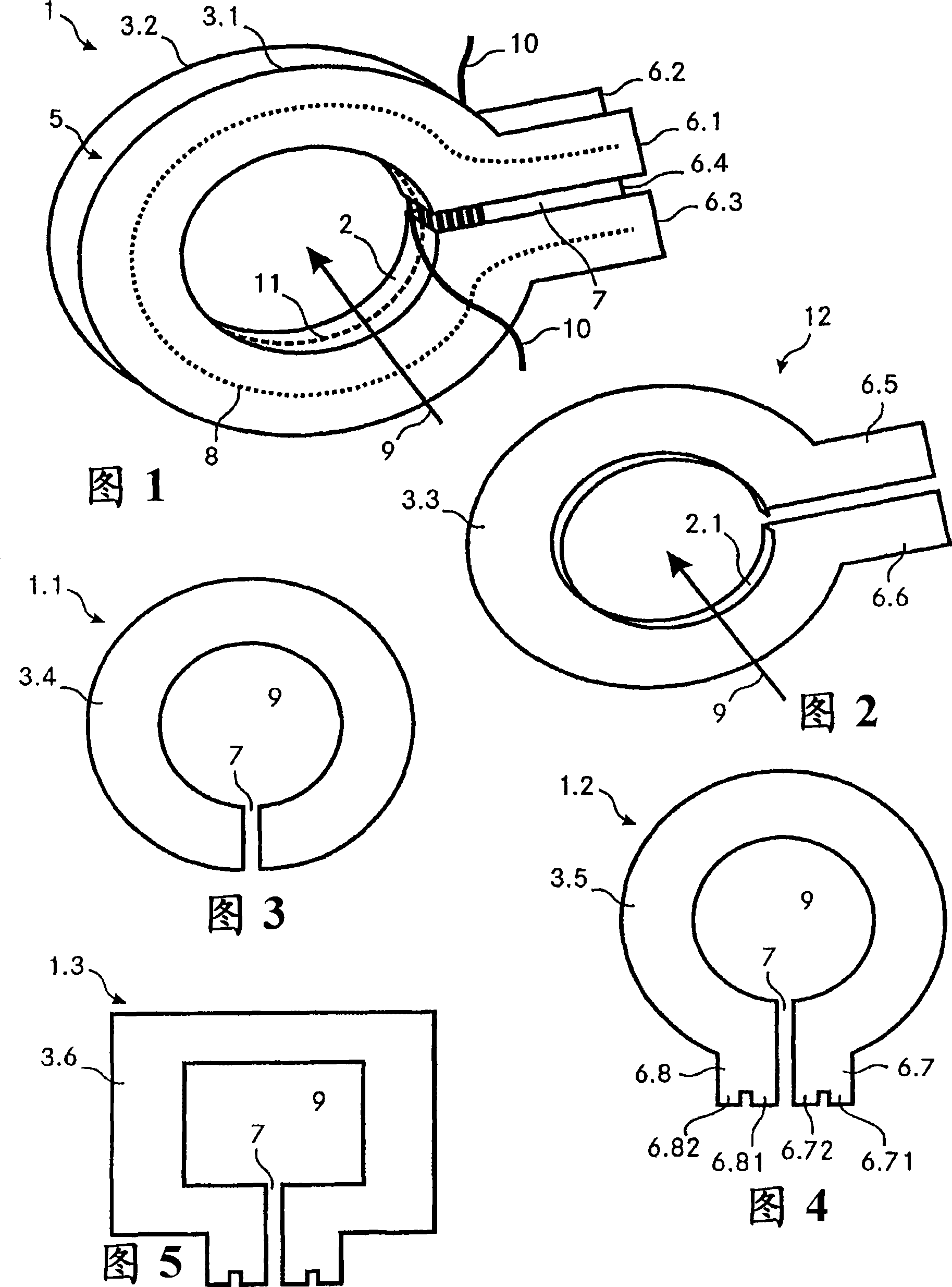
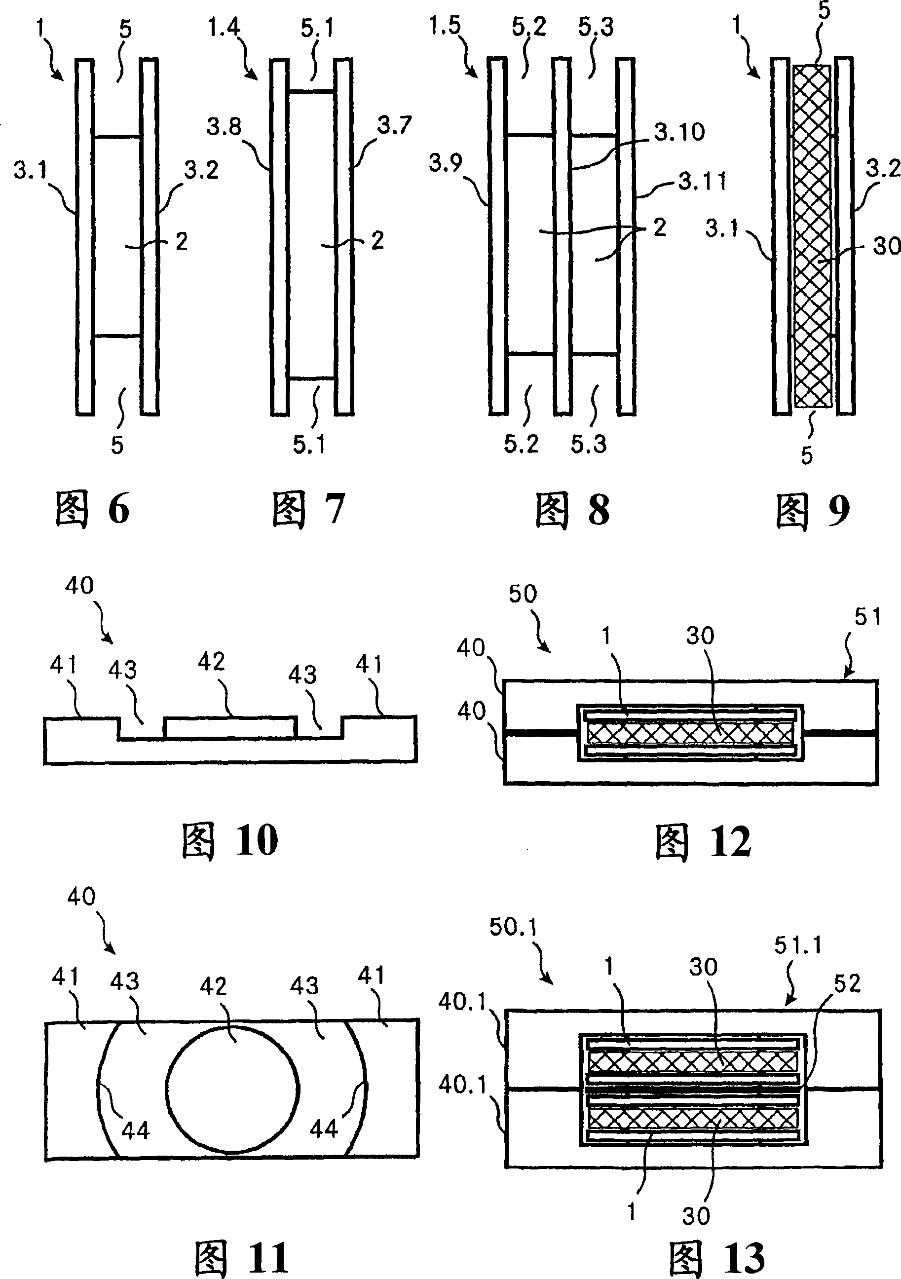
[0046] FIG. 1 shows a coil former 1 according to the invention. The coil former comprises a hollow cylindrical housing part 2 and two annular flange parts 3.1 and 3.2 at both ends of the housing part 2. The housing part 2 and the flange parts 3.1 and 3.2 are made of copper. The housing part 2 forms an opening 9 into which a magnetic core can be inserted. The outer surface of the housing part 2 and the inner side walls of the flange parts 3.1 and 3.2 form the winding chamber 5. On the right side of the coil former 1 (as shown), the coil former 1 comprises four terminals 6.1, 6.2, 6.3 and 6.4. Slit 7 separates housing part 2, flange parts 3.1 and 3.2 and terminals 6.1, 6.2, 6.3 and 6.4 to form current path 8 around opening 9. For example, a current traveling along the current path 8 in an anti-clockwise direction flows first through the terminals 6.1 and 6.2, then through the flange parts 3.1 and 3.2 and the housing part 2, and then through the terminals 6.3 and 6.4. The sli...


PUM


Abstract

The coil form (1) according to the invention for forming an inductive element includes a hollow (9) cylindrical mantle portion (2), two flange portions (3.1, 3.2) and a slit (7). The flange portions and the mantle portion form a winding chamber (5) for winding therein a wire that forms a first winding or a part of a first winding of the inductive element. The coil form (1), which is completely made of copper, forms a second coil or a winding of a second coil of the inductive element. Due to the increased contact surface between the first and the second coil the heat dissipation capabilities and the magnetic coupling between the coils are increased. This in turn results in an increased power density of the inductive element.

Description

technical field [0001] The invention relates to a coil former for forming an inductive element having a magnetic core, a first coil and a second coil, the coil former being made such that the first coil is wound around the coil former. The invention also relates to a corresponding inductive element and a method of forming such an inductive element. Background technique [0002] In the manufacture of electrical and / or electronic devices such as inductive elements such as transformers, inductors or chokes, there is a need for devices with a higher power density. However, the higher the power density of the sensing element, the lower the total losses that need to be dissipated by the smaller surface of the sensing element to keep the temperature rise constant. On the contrary, in order to meet regulatory and safety requirements, the insulation distance must be increased and an insulator must be inserted between the coil and the wire core, such as a plastic bobbin. These plast...

Claims


Application Information

Patent Timeline
Patent Type & Authority Applications(China)
IPC IPC(8): H01F5/02H01F27/28H01F27/32H01F41/06
CPCH01F41/0687H01F27/22H01F27/2847H01F27/324H01F27/323H01F2027/2819H01F2027/2861H01F41/098
Inventor J·帕克J·皮尔尼阿克P·瓦尔梅尔
Owner DET INT HLDG LTD
Why Eureka
Try Eureka