Paste coating apparatus

A gluing machine and coating technology, applied in spraying devices, devices for coating liquid on surfaces, coatings, etc., can solve problems such as inappropriateness, achieve weight reduction, less cable wear, and reduce signal errors.

Inactive Publication Date: 2007-08-29
HITACHI LTD
View PDF2 Cites 13 Cited by
  • Summary
  • Abstract
  • Description
  • Claims
  • Application Information

AI Technical Summary

Problems solved by technology

[0004] As described in the above-mentioned conventional Japanese Patent Laid-Open No. 2002-346452, along with the increase in the size of the substrate, due to the power line, signal line and other electrical harnesses and air pressure piping connected from the fixed external control panel to the door frame Increase, the number of cables following the door frame also increases, so it is not suitable for use in a clean environment due to the wear of the cables or the dust caused by the friction between the cables
[0005] In addition, even if a non-contact power feeding method is used as in JP-A-2001-211501, another movable body that moves on the movable body is provided on the movable body, and power is supplied to the other movable body, and There is no description of the transmission of control signals from the fixed part to multiple movable bodies such as the movable body and the coating head.

Method used


Image

  • Paste coating apparatus
  • Paste coating apparatus
  • Paste coating apparatus

Examples


Embodiment Construction

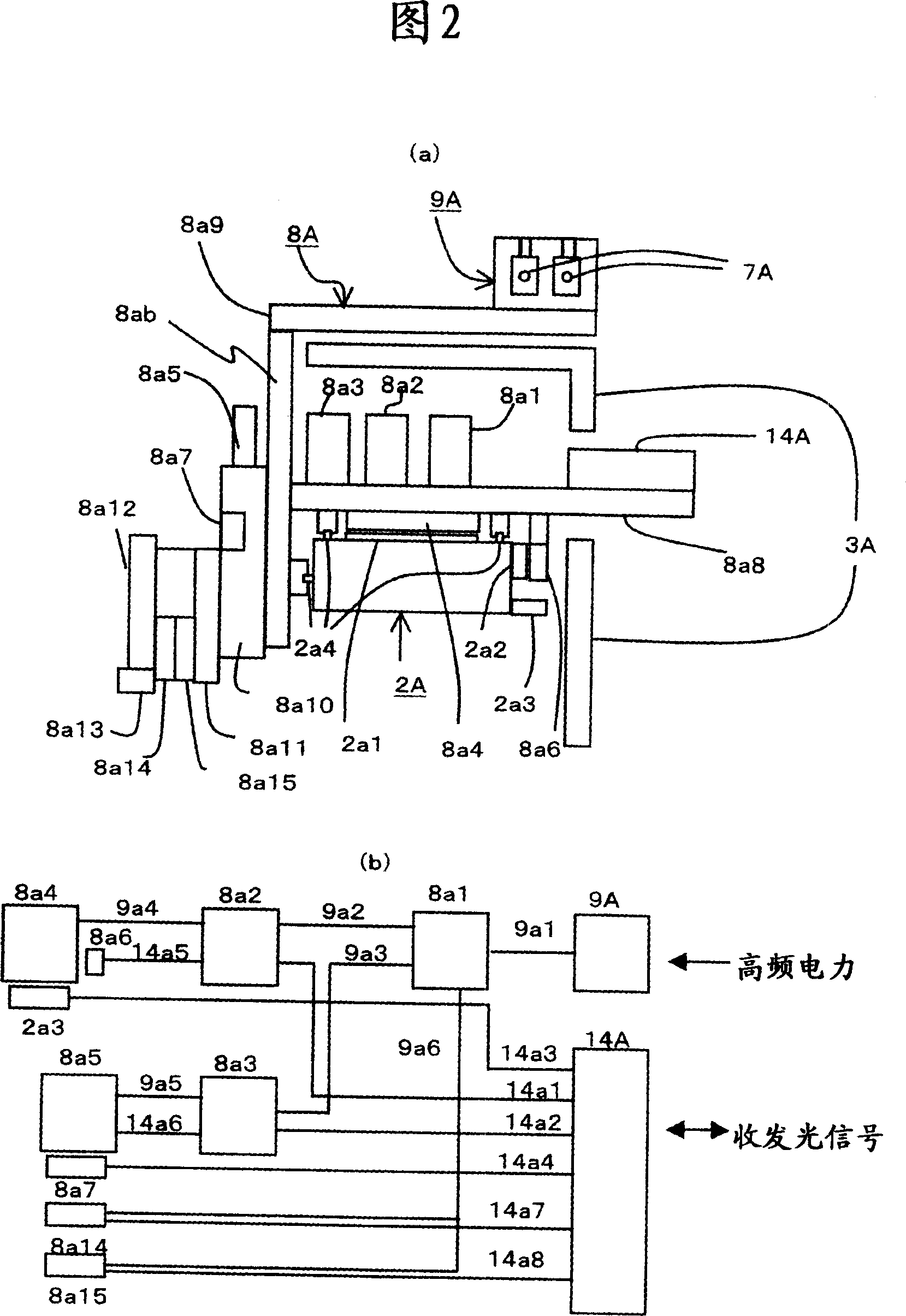
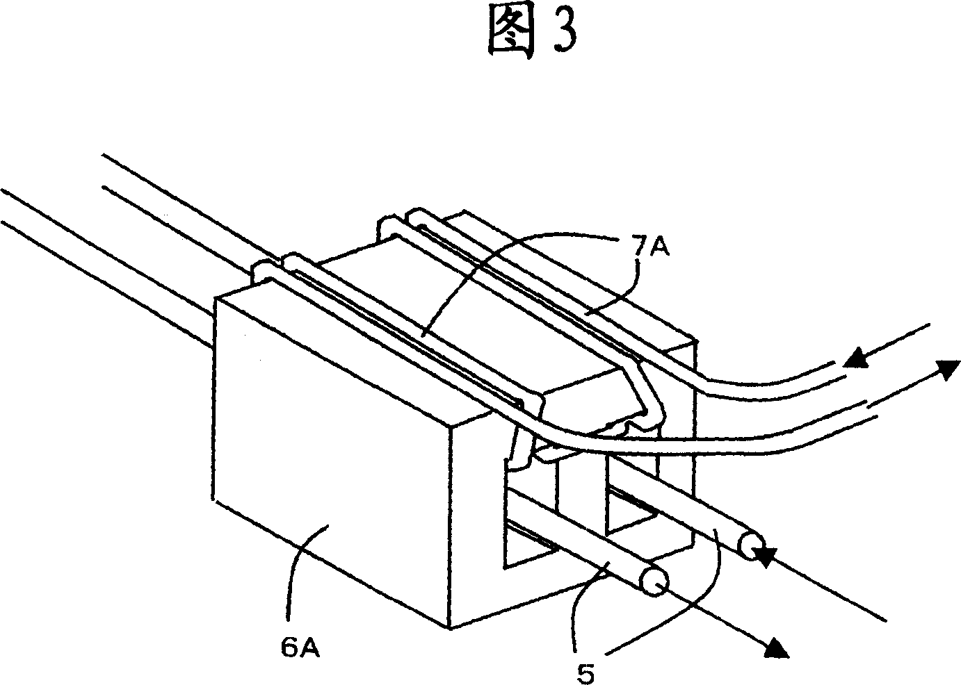
[0015] The present invention is a technology for saving power supply to a motor that drives an applicator head or power supply or signal wiring connected to a door frame for transmitting sensor signals. That is, the motor driver is set on the gantry (gantry), and the power feeding method to the driver is set as a feeder line laid in the door-type moving direction and a power-receiving pick-up (power-receiving core) installed on the door-shaped frame. In the non-contact power feeding method composed of sub), the feeding pick-up head is also set in each coating head, so that the power is received from the feeding wires wired on the door frame. Furthermore, the signal line from the main control unit to the driver is optical wireless communication. As a result, the number of movable cables following the door frame is reduced, thereby reducing dust and man-hours for wiring work. Hereinafter, its structure and operation will be described in detail using examples.

[0016] Hereinaf...


PUM


Abstract

The invention provides a glue spreader comprising many door moulding flasks reciprocating along one direction and coating head along the long rim direction of door moulding flask. A basal plate is set on platform opposite to the injection nozzle of nozzle installed on the coating head. When glue is sprayed from injection nozzle to basal plate, the relative position of basal plate and nozzle changes. In glue spreader for coating the glue figure of the desired shape on basal plate, a structure performs non-contact feeding using electromagnetic coupling between the feed line linearly set on one side of bench and current-collection core set on one side of door moulding flask, in order to transfer the control signal to moving door moulding flask. A semireflecting mirror is installed betweent the optical communication unit on one side of ground and optical communication unit on one side of movability, in order to receive the signal between the moving elements different from moving direction.

Description

technical field [0001] The present invention relates to a gluing device for coating a desired shape of gluing on a substrate in the manufacturing process of a flat plate. Background technique [0002] As a prior art, as shown in Japanese Unexamined Patent Application Publication No. 2002-346452, a glass substrate is placed on a fixed table, and it is arranged so that the main surface of the glass substrate is movable along the X-axis direction. On the gate frame, the nozzle injection port of the coating head that can move along the YZ axis direction is opposite, and while the glue filled in the glue storage cylinder is sprayed from the injection port to the substrate, the substrate and the nozzle The relative positional relationship of the substrate changes, so that the glue pattern of the desired shape is coated on the substrate. In this Japanese Unexamined Patent Application Publication No. 2002-346452, the size of the glass substrate is increased, the coating range of th...

Claims


Application Information

Patent Timeline
Patent Type & Authority Applications(China)
IPC IPC(8): B05C5/02B05C13/00B05B13/04G05D3/00
Inventor 川口洋平川隅幸宏西内章石田茂
Owner HITACHI LTD
Why Eureka
Try Eureka