Split vibration-isolation device and use
A split-type, vibration-isolation technology, which is applied to protection devices, building components, rails, etc., can solve the problems of inability to realize stock production, different sizes of connecting sleeves, and inability to accommodate connecting sleeves, etc., so as to improve the speed of supply The effect of responsiveness, compact and reasonable structure, and shortened processing cycle
- Summary
- Abstract
- Description
- Claims
- Application Information
AI Technical Summary
Problems solved by technology
Method used
Image
Examples
Embodiment 1
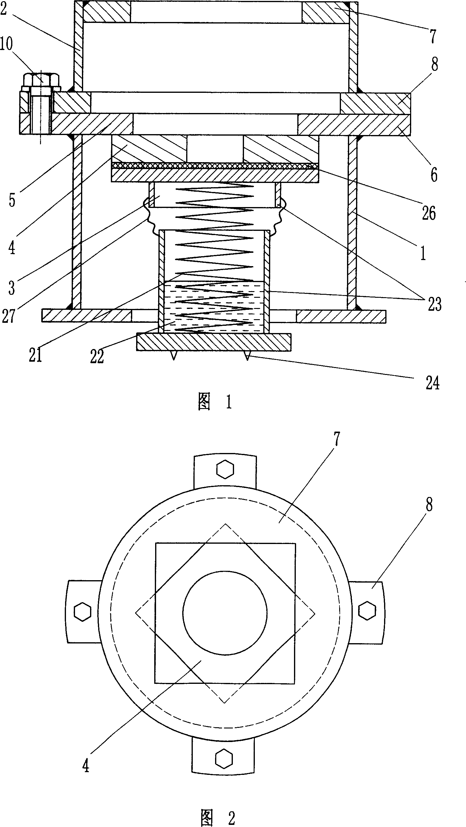
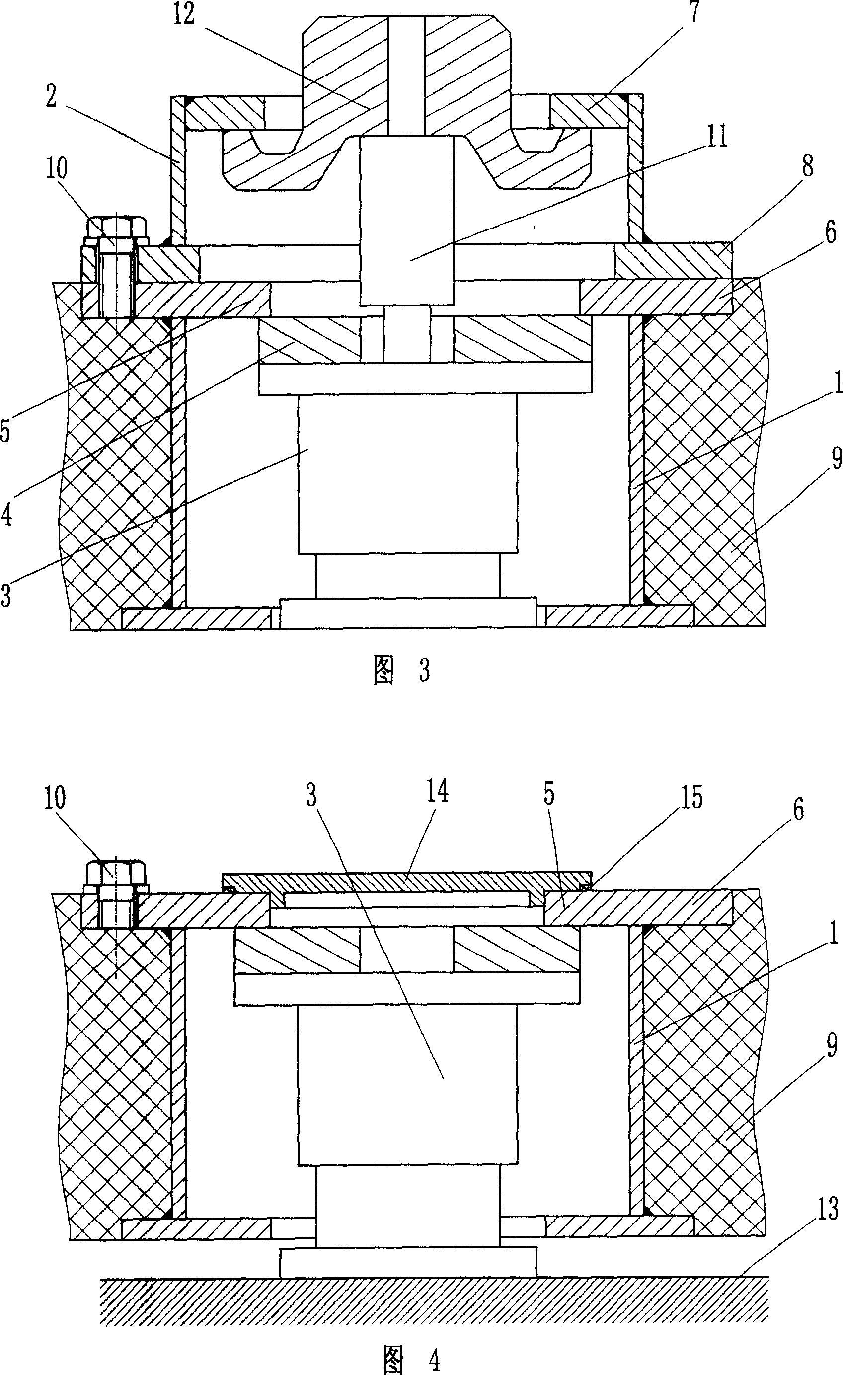
[0035] As shown in Figure 1, the split type vibration isolation device of the present invention includes a lower sleeve 1, an upper sleeve 2, a spring vibration isolator 3 and a gasket 4, wherein, the upper part of the lower sleeve 1 is provided with a support block 5, which is The simplified structure integrates the supporting block 5 and the connecting flange 6 at the top of the lower sleeve, and the upper part of the upper sleeve 2 is provided with a jacking block 7 . The lower sleeve 1 and the upper sleeve 2 are coupled together by means of the bolts 10 arranged between the connecting flange 6 at the top end of the lower sleeve 1 and the connecting flange 8 at the bottom end of the upper sleeve 2 . The thickness of the lower sleeve 1 is adapted to the thickness of the floating plate 9 .
[0036]The spring vibration isolator 3 includes a spring housing and a spring 21. The spring 21 is located in the spring housing 23 and is a helical spring with suitable rigidity in the ve...
Embodiment 2
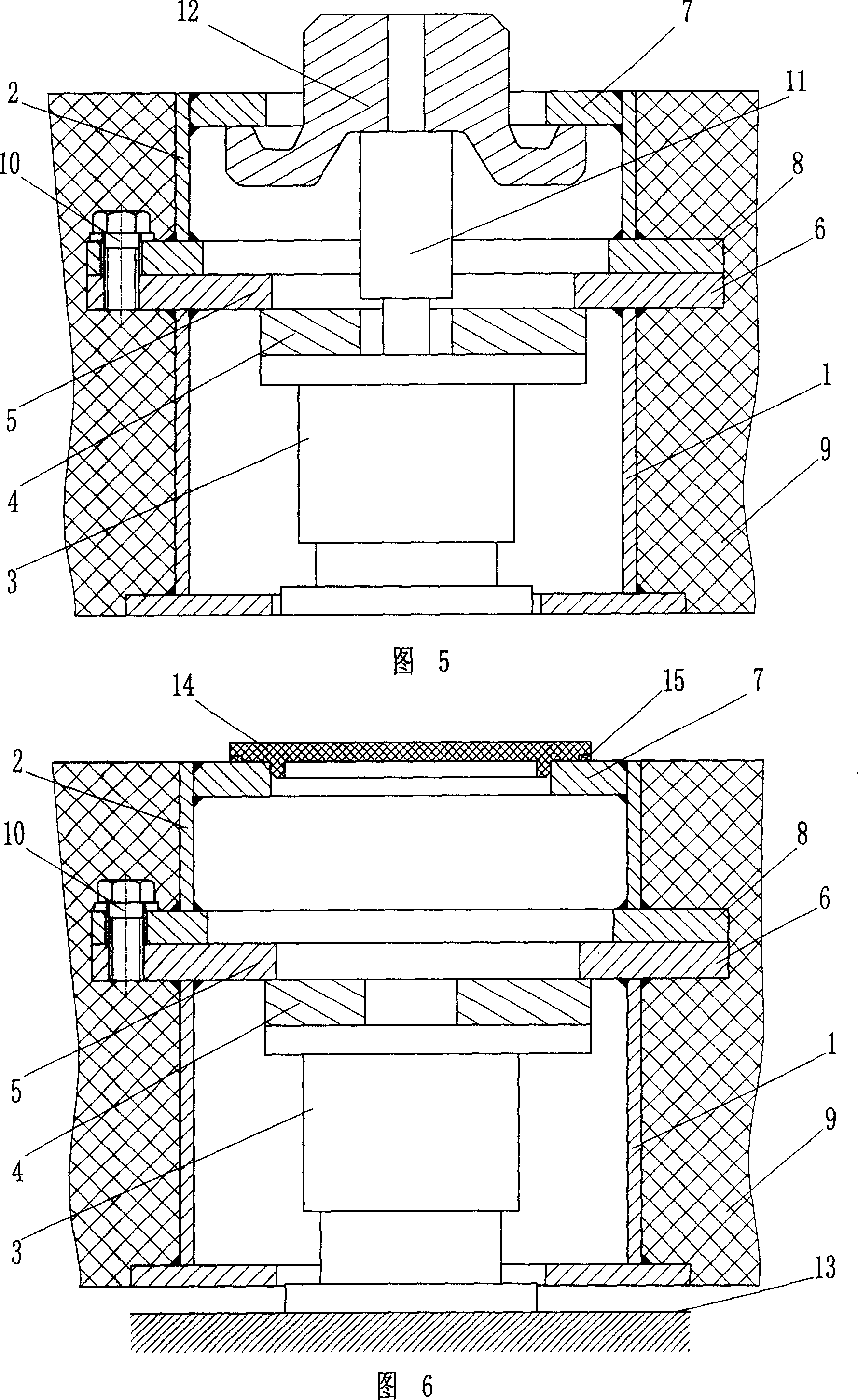
[0042] As shown in Figure 1, Figure 5 and Figure 6, the difference from Embodiment 1 is that the upper sleeve 2 and the lower sleeve 1 are fixedly connected and preset in the floating plate 9. A dustproof cover 14 and a sealing gasket 15 are arranged above the sleeve 2 . Of course, the dustproof cover 14 can also be completely embedded in the upper sleeve 2, which is more attractive in appearance.
[0043] When in use, the lower sleeve 1 can be standardized and produced in stock, and the upper sleeve 2 can be processed according to the actual thickness of the floating plate 9 before delivery, and the height of the connecting sleeve can be quickly matched in the factory or on the construction site, so that there is It is beneficial to further shorten the processing cycle, improve construction efficiency, and can better meet the vibration isolation requirements of floating slabs with different thicknesses or floating slabs with continuously changing thicknesses. In addition to ...
Embodiment 3
[0045] As shown in Figure 7, the difference from Embodiment 1 is that the connecting flange at the bottom of the upper sleeve 2 is canceled, and the pin holes provided on the side walls of the lower sleeve 1 and the upper sleeve 2 are used to connect the two through pins 16 together.
[0046] The structure of the upper sleeve 2 adopting this connection method is simpler, less material is used, and the cost is correspondingly lower. The space above the supporting block 5 of the lower sleeve 1 can be used to place a dust cover (not shown in the figure) after the upper sleeve 2 is removed, and the space utilization is more compact and more reasonable. Of course, threaded holes can also be provided, and bolts can be used instead of pins to realize the connection.
[0047] In addition to the cooperating connection between the pin holes and the pin bolts, it is also possible to set the pin bolts on the side walls of the upper and lower sleeves, and the upper and lower sleeves are c...
PUM
 Abstract
Description
Claims
Application Information
 - R&D
- Intellectual Property
- Life Sciences
- Materials
- Tech Scout
- Unparalleled Data Quality
- Higher Quality Content
- 60% Fewer Hallucinations
Browse by: Latest US Patents, China's latest patents, Technical Efficacy Thesaurus, Application Domain, Technology Topic, Popular Technical Reports.
© 2025 PatSnap. All rights reserved.Legal|Privacy policy|Modern Slavery Act Transparency Statement|Sitemap|About US| Contact US: help@patsnap.com


