Zoom lens system and optical device using thereof

A zoom lens and lens group technology, applied in optics, optical components, instruments, etc., can solve problems such as blurred images and reduced image performance

Inactive Publication Date: 2007-08-29
NIKON CORP
View PDF3 Cites 21 Cited by
  • Summary
  • Abstract
  • Description
  • Claims
  • Application Information

AI Technical Summary

Problems solved by technology

[0006] In such zoom lens systems, the problem is that small camera shakes that occur during photography, such as when the photographer presses the shutter button, result in blurred images that degrade image performance

Method used


Image

  • Zoom lens system and optical device using thereof
  • Zoom lens system and optical device using thereof
  • Zoom lens system and optical device using thereof

Examples


no. 1 example

[0080] The zoom lens system according to the first embodiment will be described below.

[0081] The zoom lens system according to the first embodiment of the present invention, in order from the object, includes: a first lens group having a positive refractive power and having an optical path bending element for bending an optical path by substantially 90 degrees; having a negative refractive power the second lens group having positive refractive power; the third lens group having positive refractive power; and the fourth lens group having positive refractive power. When the focal length changes from the wide-angle end state to the telephoto end state, that is, when zooming, the first lens group and the third lens group are fixed relative to the image plane, the second lens group moves toward the image plane, and the fourth lens group moves toward the image plane. The lens groups initially move toward the object and then move toward the image plane such that the distance betwe...

example 1

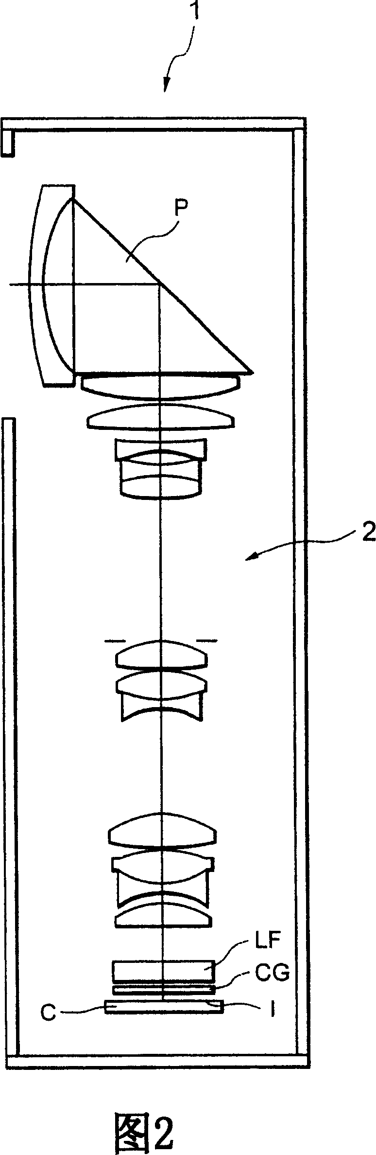
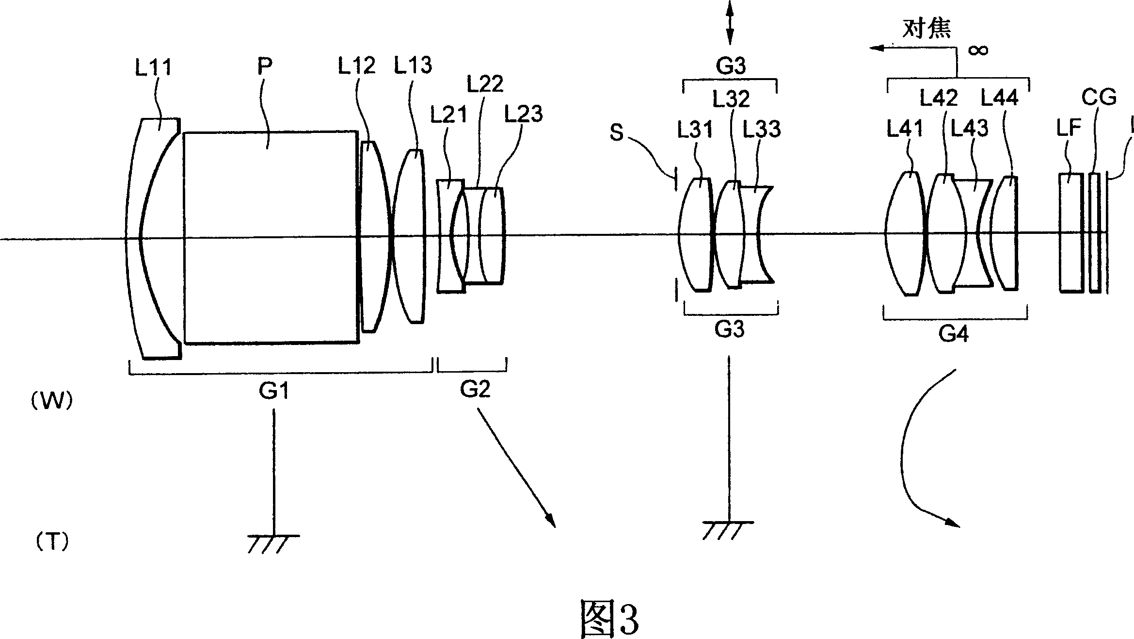
[0105] 3 is a schematic diagram showing a lens configuration of a zoom lens system according to Example 1 of the first embodiment. Although the zoom lens system according to Example 1 deflects its optical path by 90 degrees as shown in FIG. 2 , the optical path extends in FIG. 3 .

[0106] In FIG. 3 , the zoom lens system according to Example 1 is composed, in order from the object, of the following components: a first lens group G1 having a positive refractive power and having a rectangular prism P for bending the optical path by substantially 90 degrees ; the second lens group G2 with negative refractive power; the third lens group G3 with positive refractive power; and the fourth lens group G4 with positive refractive power. When the focal length changes from the wide-angle end state W to the telephoto end state T state, the first lens group G1 and the third lens group G3 are fixed relative to the image plane I, and the second lens group G2 moves toward the image plane I ,...

example 2

[0203] 8 is a schematic diagram showing a lens configuration of a zoom lens system according to Example 2 of the first embodiment. Although the zoom lens system according to Example 2 deflects its optical path by 90 degrees as shown in FIG. 2 , the optical path extends in FIG. 8 .

[0204] In FIG. 8, the zoom lens system according to Example 2 is composed, in order from the object, of the following components: a first lens group having positive refractive power and having a rectangular prism P for bending the optical path by substantially 90 degrees G1; a second lens group G2 having negative refractive power; a third lens group G3 having positive refractive power; and a fourth lens group G4 having positive refractive power. When the focal length changes from the wide-angle end state W to the telephoto end state T state, the first lens group G1 and the third lens group G3 are fixed relative to the image plane I, and the second lens group G2 moves toward the image plane I , and...


PUM


Abstract

The present invention provides a zoom lens system having a vibration reduction function, suitable for a compact optical device using a solid-state imaging device. The system includes, in order from an object, a first lens group having positive power and a bending member for bending the optical path by about 90 DEG , a second lens group having negative power, a third lens group having positive power, and a fourth lens group having positive power. Upon zooming from a wide-angle end state to a telephoto end state, the first and third lens groups are fixed with respect to an image plane, the second lens group is moved to the image, and the fourth lens group is moved at first to the object and then to the image plane. An image blur on the image plane caused by a camera shake is corrected by moving the third lens group perpendicularly to the optical axis.

Description

[0001] The contents of the following prior applications are hereby incorporated by reference: [0002] Japanese Patent Application No. 2006-041510 filed on February 17, 2006, and [0003] Japanese Patent Application No. 2006-041515 filed on February 17, 2006. technical field [0004] The present invention relates to zoom lens systems and optical devices utilizing such lens systems. Background technique [0005] A bent zoom lens system suitable for a camera using a solid-state imaging device or the like (hereinafter simply referred to as a zoom lens system) having a zoom ratio of about 3 to 7 by using a rectangular prism for bending an optical path inside the camera has been proposed. (eg Japanese Patent Application Laid-Open No. 2005-215165). [0006] In such zoom lens systems, the problem is that small camera shakes that occur during photography, such as when the photographer presses the shutter button, cause blurred images and degrade image performance. Therefore, it is...

Claims


Application Information

Patent Timeline
Patent Type & Authority Applications(China)
IPC IPC(8): G02B15/16G02B15/14G02B15/177G02B9/34G02B27/64
Inventor 荒井大作
Owner NIKON CORP
Why Eureka
Try Eureka