Photocurrent monitoring circuit for transimpedance amplifier

A technology of transimpedance amplifier and monitoring circuit, applied in the field of optical communication, can solve the problems of PIN not working normally, unable to adapt to photocurrent input signal, large error, etc., to achieve high precision effect

Inactive Publication Date: 2007-08-29
FENGHUO COMM SCI & TECH CO LTD
View PDF0 Cites 15 Cited by
  • Summary
  • Abstract
  • Description
  • Claims
  • Application Information

AI Technical Summary

Problems solved by technology

[0003] Existing photocurrent monitoring circuits mostly use linear sampling circuits for monitoring circuits. The disadvantage of this type of sampling circuit is that if the sensitivity of the sampling circuit is set low, when a small signal photocurrent is input, because the signal amplitude is very small, it will The accuracy of the output monitoring signal is very low and the error is large; if the sensitivity of the sampling circuit is set higher, when a large signal photocurrent is input, a considerable sampling voltage will be generated at both ends of the sampling circuit, which may cause the PIN to fail to work normally.
Therefore, it cannot adapt to the photocurrent input signal with a large dynamic range.

Method used


Image

  • Photocurrent monitoring circuit for transimpedance amplifier

Examples


Embodiment Construction

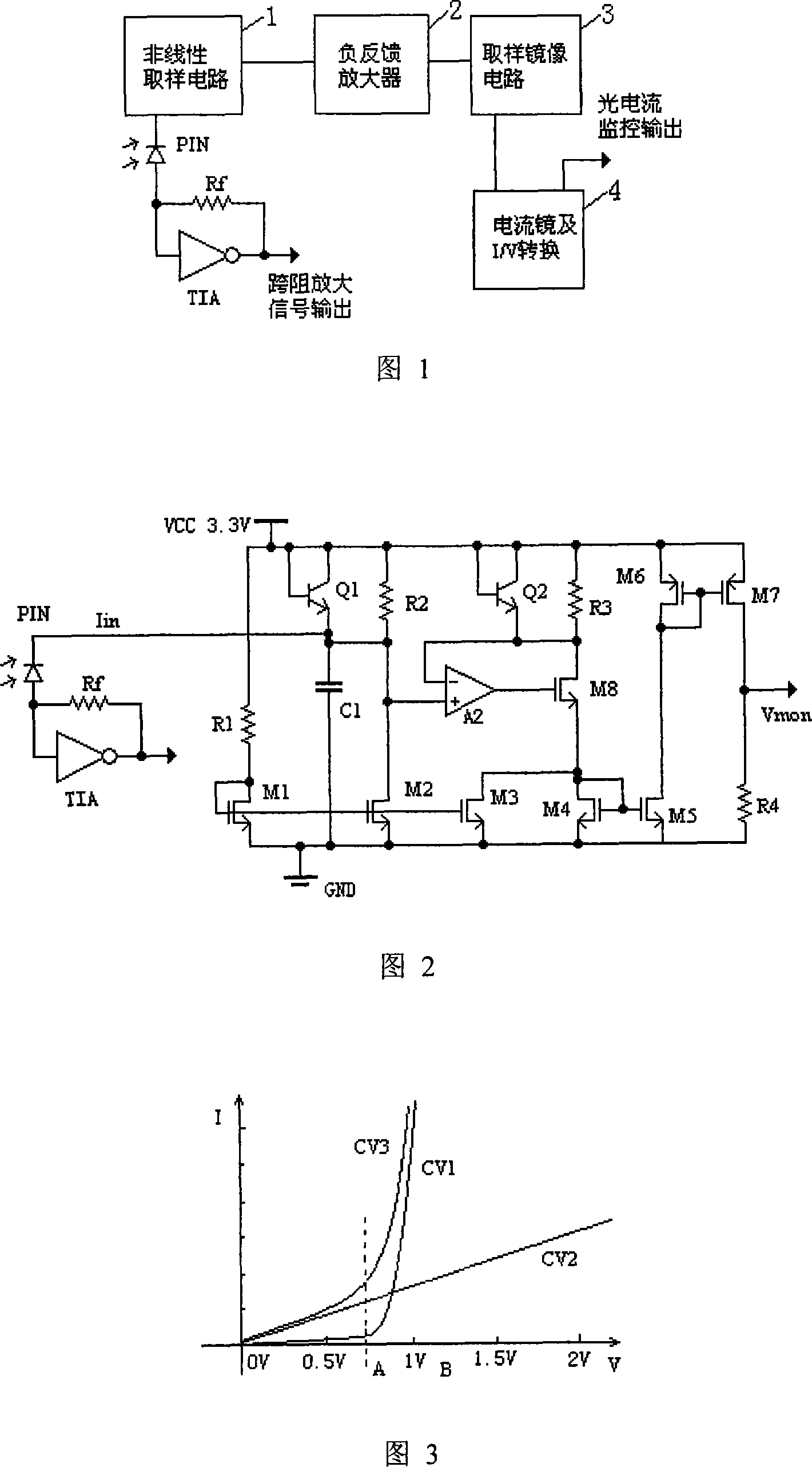
[0010] Fig. 1 is the circuit principle block diagram of the present invention, and this photocurrent monitoring circuit is mainly made of nonlinear sampling circuit 1, negative feedback amplifier 2, sampling mirror circuit 3, current mirror and I / V conversion circuit 4

[0011] In Figure 2, PIN is the photodetector, the transimpedance amplifier TIA and the resistor Rf form the main body of the transimpedance amplifier, and the rest is the photocurrent monitoring circuit. For the photocurrent monitoring circuit, the transistor Q1 and the resistor R2 form a nonlinear sampling circuit; the amplifier A2 and the field effect transistor M8 form a negative feedback amplifier; the voltage signal is sent to the non-inverting input of the amplifier A2. The voltage signal passes through the negative feedback amplifier composed of the amplifier A2 and the field effect transistor M8, and the mirror voltage equal to the sampling voltage of the same input terminal of the amplifier is obtained...


PUM


Abstract

The photocurrent monitoring circuit (PMC) includes non-linear sampling circuit, negative feedback amplifier, sampling mirror image circuit, current mirror, and I/V switching circuit etc. The non-linear sampling circuit consists of transistor Q1 and resistance R2. The negative feedback amplifier is composed of amplifier A2 and field effect tube M8. The sampling mirror image circuit is composed of transistor Q2 and resistance R3. Current mirror, and I/V switching circuit include field effect tubes M4, M5, M6, M7 and resistance R4. Being able to monitor the input photocurrent in large dynamic range, PMC still keeps high precision. When PMC monitors the input photocurrent in large dynamic range, normal operation of main body of magnifier is not influenced.

Description

technical field [0001] The invention relates to the field of optical communication, in particular to a photocurrent monitoring circuit for a transimpedance amplifier. Background technique [0002] Researchers at home and abroad have done a lot of research on transimpedance amplifier TIA. If the TIA used in the optical communication field has a photocurrent monitoring function, it will greatly facilitate the user's system design. [0003] Existing photocurrent monitoring circuits mostly use linear sampling circuits for monitoring circuits. The disadvantage of this type of sampling circuit is that if the sensitivity of the sampling circuit is set low, when a small signal photocurrent is input, because the signal amplitude is very small, it will The accuracy of the output monitoring signal is very low and the error is large; if the sensitivity of the sampling circuit is set higher, when a large signal photocurrent is input, a considerable sampling voltage will be generated at ...

Claims


Application Information

Patent Timeline
Patent Type & Authority Applications(China)
IPC IPC(8): H04B10/08H01J40/14H03F3/08
Inventor 蒋湘
Owner FENGHUO COMM SCI & TECH CO LTD
Why Eureka
Try Eureka