

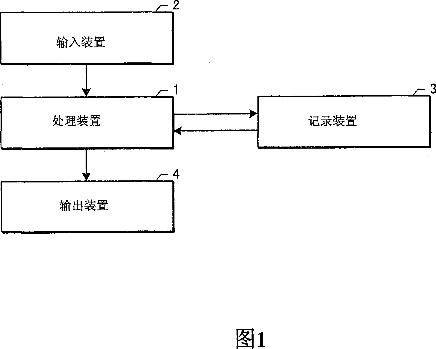
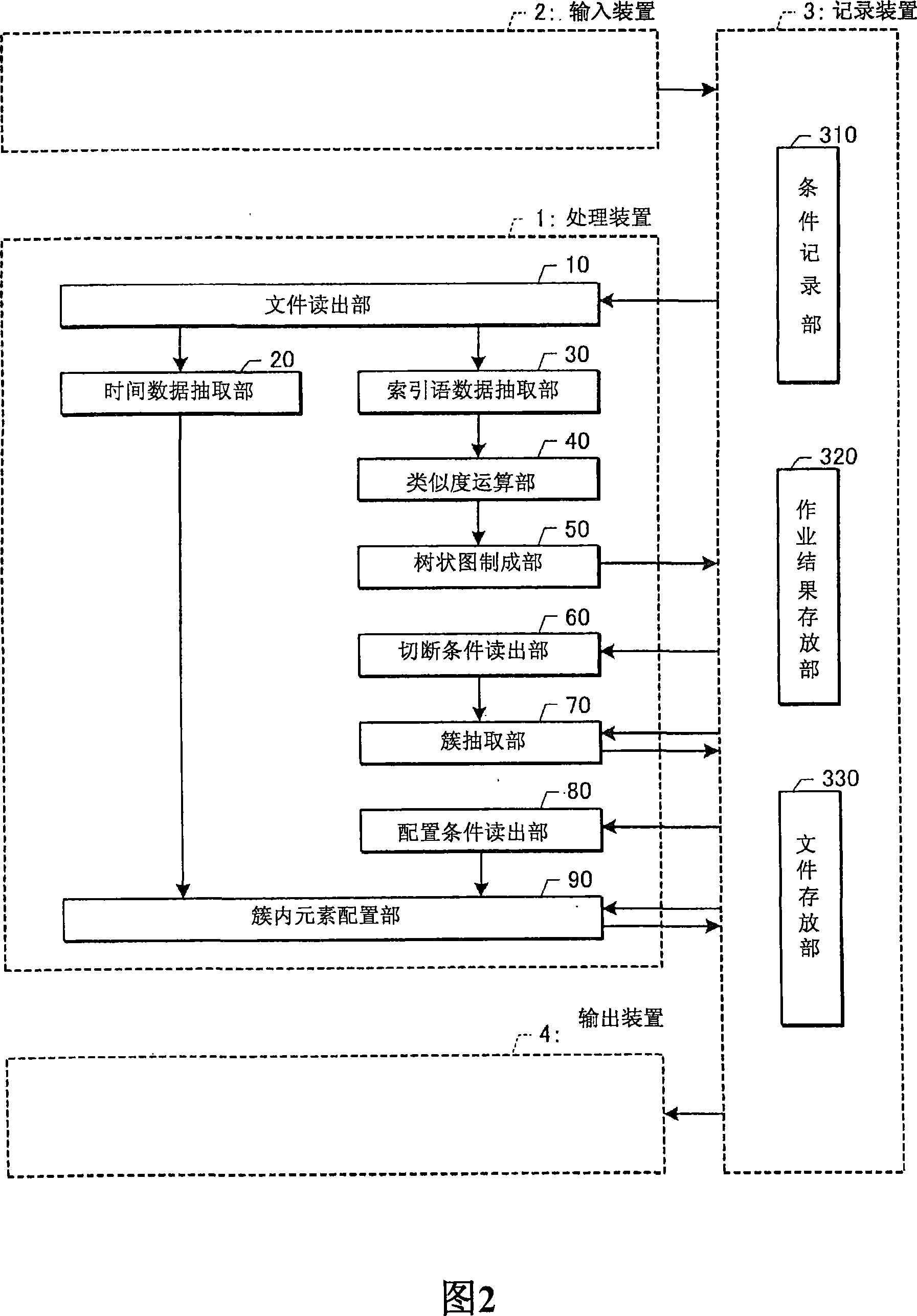
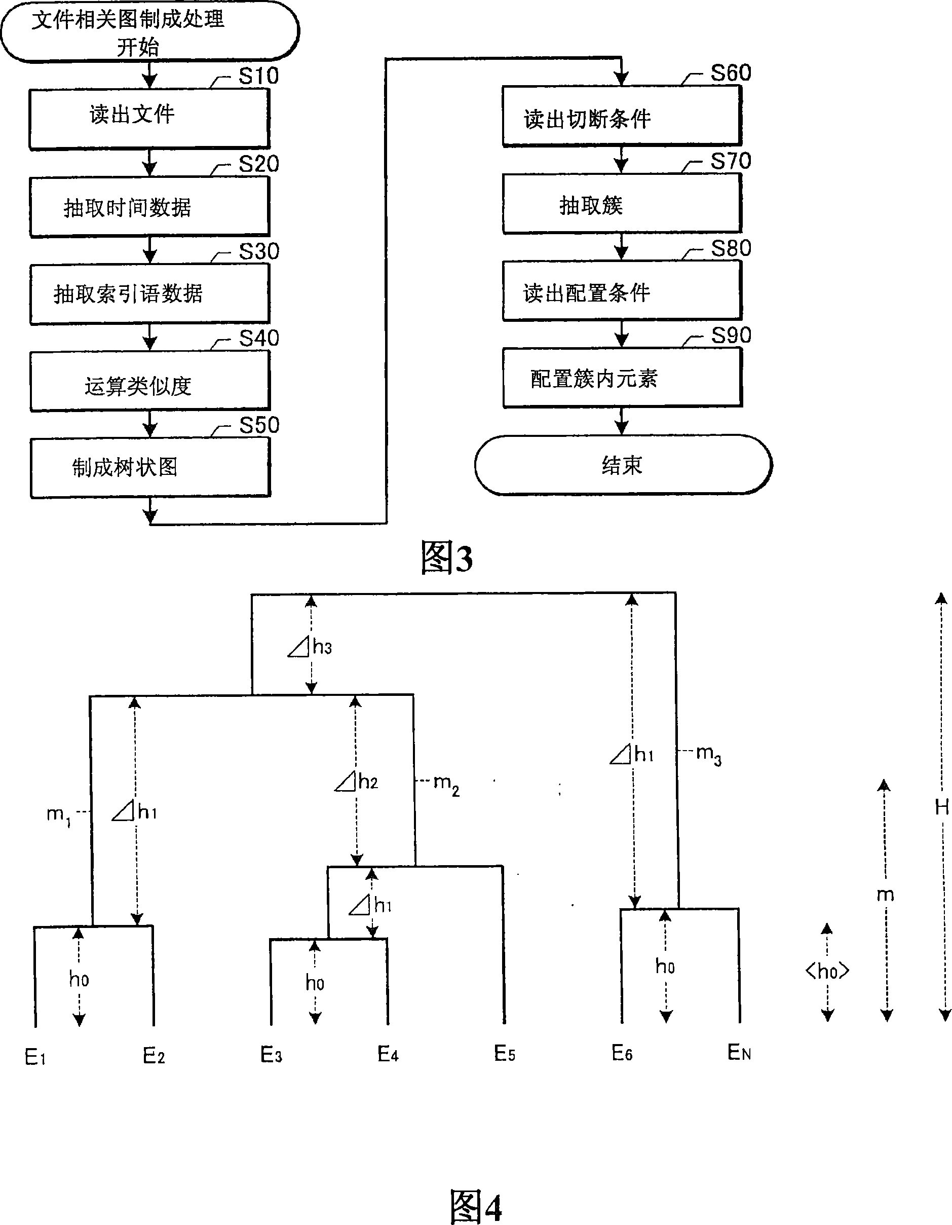
Device for drawing document correlation diagram where documents are arranged in time series
A correlative diagram and time sequence technology, applied to computer parts, instruments, calculations, etc., can solve problems such as accumulation of deviations, inability to properly represent the temporal development of the field, and ambiguous branch meanings, and achieve the effect of improving misclassification
- Summary
- Abstract
- Description
- Claims
- Application Information
AI Technical Summary
Problems solved by technology
Method used
Image

Examples
Embodiment 2
[0284]
[0285] In the Codimensional Reduction Method (Codimensional Reduction Method), as in Embodiment 1 (Balanced Cutting Method; BC Method), association rules are used to determine the cutting position of the dendrogram. In embodiment 1, the parameters that can be obtained according to the geometric shape of the dendrogram are used, and the combination height between elements is used as the cutting position, while in this embodiment 2, the index dimension that represents the difference between the document element vectors is used to determine Decide where to cut.
[0286] Since the basic description related to association rule analysis has been done in Embodiment 1, it will be omitted. First, the differences between Embodiment 2 and Embodiment 1 will be described for the parameters used in association rule analysis in Embodiment 2.
[0287]
[0288] When a certain node (node) c is given in the dendrogram, its combination level is represented by an integer i(c...
Embodiment 3
[0324]
[0325] In the Cell Division Method, after cutting the dendrogram at the cutting height α determined by a certain method and extracting the parent cluster, only the file elements belonging to each parent cluster are used in order to divide each parent cluster into sub-clusters , again making a dendrogram of that section. When creating the partial dendrogram, the index dimension for which the deviation value of the document element vector component in the parent cluster is smaller than the value determined by a predetermined method is removed and analyzed.
[0326]
[0327] Fig. 11 is a flowchart illustrating a cluster extraction procedure in Example 3 (cell division method; CD method). This flowchart shows the sequence of the third embodiment in more detail than in FIG. 3 . For the same steps as in Fig. 3, 300 is added to the step number in Fig. 3, and the last two digits are the same step numbers as in Fig. 3, and the description repeated with Fig. 3 is so...
Embodiment 6
[0444]
[0445] In Pole-and-Line Arrangement, for a cluster with a small number of file elements, the arrangement within the cluster is determined based on time data and dendrogram configuration data.
[0446]
[0447] Fig. 30 is a flow chart illustrating an arrangement process within a cluster in Embodiment 6 (rod and fishing arrangement; PLA). In this flow chart, the premise is that clusters are extracted through the processing before step S70 (cluster extraction) in FIG. 3, and the parts of step S80 (reading of configuration conditions) and step S90 (arrangement of elements in clusters) in FIG. 3 are shown in more detail. The sequence of the present embodiment 6 has been completed. For the same steps as in Fig. 3, 600 is added to the step number in Fig. 3, and the last two digits are the same as those in Fig. 3, and the description repeated with Fig. 3 is sometimes omitted.
[0448] FIG. 31 is a diagram showing an example of arranging a tree diagram in the in...
PUM
 Abstract
Description
Claims
Application Information