Supercharge Your Innovation With Domain-Expert AI Agents!

Method and related apparatus for controlling rotation frequency of spindle in optical disc drive

A technology of rotation frequency and spindle, which is applied in the field of controlling the rotation frequency of the spindle of an optical drive, and can solve problems such as increasing the design complexity of the control system.

Inactive Publication Date: 2011-02-16
MEDIATEK INC
View PDF0 Cites 0 Cited by
  • Summary
  • Abstract
  • Description
  • Claims
  • Application Information

AI Technical Summary

Problems solved by technology

The rotation control signal S CONT The drastic frequency change will increase the complexity of the control system design, and in the case of considering the stability of the adjustment program, it will force the system designer to consider more design parameters

Method used


Image

  • Method and related apparatus for controlling rotation frequency of spindle in optical disc drive
  • Method and related apparatus for controlling rotation frequency of spindle in optical disc drive
  • Method and related apparatus for controlling rotation frequency of spindle in optical disc drive

Examples


Embodiment Construction

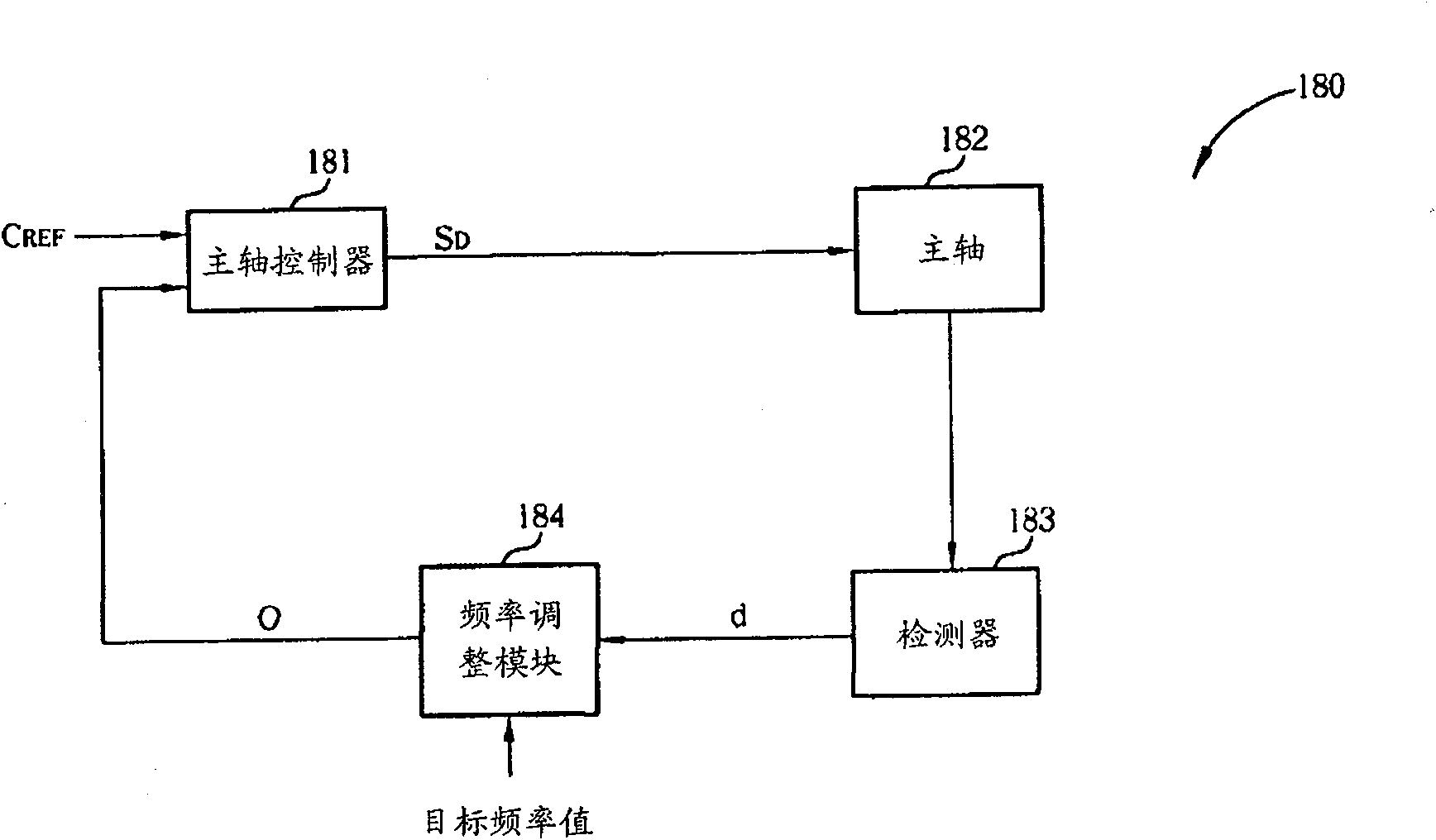
[0068] Please refer to figure 2 , which is a block diagram of a control circuit 180 according to the first embodiment of the present invention. The control circuit 180 is applied in an optical drive, and the optical drive operates in a constant angular velocity mode. The control circuit 180 includes a spindle controller 181 , a spindle 182 , a detector 183 , and a frequency adjustment module 184 . The control circuit 180 compares an output signal O with a reference clock C REF , to generate a drive control signal S D to drive the main shaft 182 to rotate at a predetermined rotational frequency. The detector 183 detects the rotation frequency of the spindle 182 and generates a detection signal d corresponding to the constant surface speed mode. The frequency adjustment module 184 receives a target frequency value, and increases the frequency of the detection signal d. Therefore, the frequency adjustment module 184 outputs an output signal O having the target frequency to ...


PUM


Abstract

The present invention provides a method and related apparatus for controlling rotation frequency of spindle in optical disc drive. The control circuit comprising: a spindle controller, electrically coupled to the spindle, for driving the spindle to rotate an optical disc according to a rotation control signal; a detector, electrically coupled to the spindle controller, for detecting the rotation frequency and for generating detecting signals; a frequency-adjusting module, electrically coupled to the detector, for adjusting at least one of the detecting signals to reduce a rotation frequency difference between detecting signals; a signal selector, electrically coupled to the frequency-adjusting module, for receiving output signals generated from the frequency-adjusting module and then outputting the rotation control signal.

Description

technical field [0001] The invention relates to optical drive technology, especially to a method and a related device for controlling the rotation frequency of the main shaft of the optical drive. Background technique [0002] In the prior art, an optical drive has two different operation modes when accessing an optical disc. The first is a constant linear velocity (CLV) mode, and the second is a constant angular velocity (CAV) mode. Depending on the needs, the optical drive will use different modes to read or write data to the optical disc. [0003] However, in these two operation modes, the control methods of the spindle are also different. In the constant angular velocity mode, a hall sensor is used to sense the rotation frequency of the spindle, and the servo system of the optical drive will generate a rotation control signal to control the rotation frequency of the spindle between 10Hz and 100Hz. In the constant line speed mode, the rotation frequency of the spindle ...

Claims


Application Information

Patent Timeline
Patent Type & Authority Patents(China)
IPC IPC(8): G11B19/28G11B7/00
CPCG11B19/24H02P6/08
Inventor 林郁轩杨金彬陈志清吴国辉
Owner MEDIATEK INC
Features
  • R&D
  • Intellectual Property
  • Life Sciences
  • Materials
  • Tech Scout
  • Unparalleled Data Quality
  • Higher Quality Content
  • 60% Fewer Hallucinations
Learn More