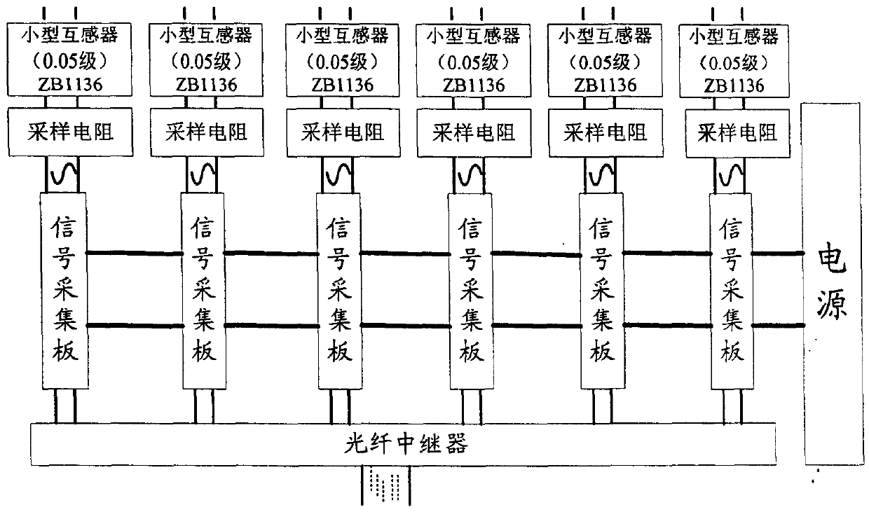
Local digitizer of analog mutual inductor
A transformer and analog technology, applied in the direction of inductors, transformers, electrical component structure associations, etc., can solve the problems of laser power supply, high cost of photocells, high requirements for primary power supply, and increase the overall cost, etc., to achieve electrical isolation, Effect of eliminating pressure drop and improving accuracy
Inactive Publication Date: 2007-09-05
北京浩霆光电技术有限责任公司
View PDF0 Cites 4 Cited by
- Summary
- Abstract
- Description
- Claims
- Application Information
AI Technical Summary
Problems solved by technology
However, the primary converter of the existing electronic transformer works on the high-voltage side. For the active type, it has high requirements for the primary power supply. At present, the optical energy supply method of the laser is mainly used, and its life expectancy needs to be tested. Product reliability Experience is still accumulating, and it is in the experimental stage of product operation. In addition, the cost of laser power supply and photocells is very high, which increases the overall cost.
Method used
View moreImage
Smart ImageViewing Examples
Examples
Embodiment Construction
Login to View More PUM
 Abstract
The invention is concerned with the in-place digitization equipment of simulation quantity instrument transformer. It consists of: N transducer with small size, N signal collecting board and the power supply. The numeric area of N is the positive integer from 1 to 6; the connection of each part is: each inputting end of the small transducer connects with one outputting end of the traditional electromagnetism instrument transformer, each outputting end of the small transducer connects with the signal collecting board and forms the signal processing unit, N signal processing units connects with the power supply. The equipment solves the magnetic saturation problem of the traditional high voltage instrument transformer; the invention is with high accuracy in computation; convenient maintenance and operation; capability of working under long shift, stable and low cost.
Description
technical field The invention belongs to the technical field of electric power equipment, and in particular relates to the on-site digital transformation technology of traditional transformers. Background technique In the construction of substations, traditional electromagnetic transformers have been the mainstay for decades, divided into two types: current transformers and voltage transformers, GB1207 and GB1208. Its output current is 5A / 1A, voltage 100V / analog signal, which is directly transmitted to the secondary equipment such as relay protection in the control room through long-distance cables. The advantages of this type of transformer are: a large number of long-term operating experience; long life, the general design life is 30 years; except for high-voltage and ultra-high-voltage grades, the cost is low. Its disadvantages are: magnetic saturation phenomenon; SF6 and other non-environmentally friendly gases or liquids are used as insulating materials, and accident...
Claims
Login to View More Application Information
Patent Timeline
 IPC IPC(8): H01F38/34H01F27/40
Inventor 汪良明罗承沐张贵新
Owner 北京浩霆光电技术有限责任公司
Features
- R&D
- Intellectual Property
- Life Sciences
- Materials
- Tech Scout
- Unparalleled Data Quality
- Higher Quality Content
- 60% Fewer Hallucinations
Learn More Browse by: Latest US Patents, China's latest patents, Technical Efficacy Thesaurus, Application Domain, Technology Topic, Popular Technical Reports.
© 2025 PatSnap. All rights reserved.Legal|Privacy policy|Modern Slavery Act Transparency Statement|Sitemap|About US| Contact US: help@patsnap.com


