
Light-emitting diodes driving circuit

A technology of light-emitting diodes and driving circuits, applied in the field of driving circuits, can solve problems such as speeding up the lighting speed of light-emitting diodes, and achieve the effect of suppressing current overshoot

Inactive Publication Date: 2007-09-05
苏州日月成科技有限公司
View PDF0 Cites 2 Cited by
  • Summary
  • Abstract
  • Description
  • Claims
  • Application Information

AI Technical Summary

Problems solved by technology

[0007] The above-mentioned driving circuit obviously cannot meet the requirement of accelerating the lighting speed of the LED, therefore, it is necessary to design a driving circuit to solve the shortcomings of the existing driving circuit

Method used


Image

  • Light-emitting diodes driving circuit
  • Light-emitting diodes driving circuit

Examples


Embodiment Construction

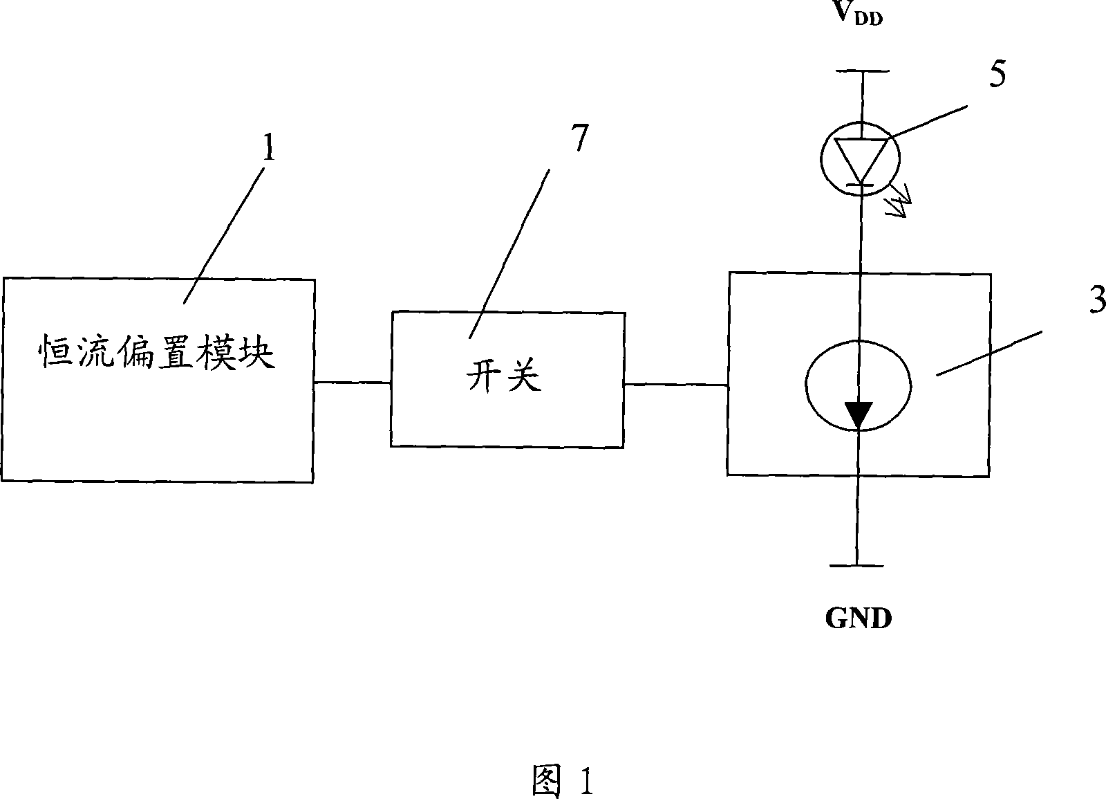
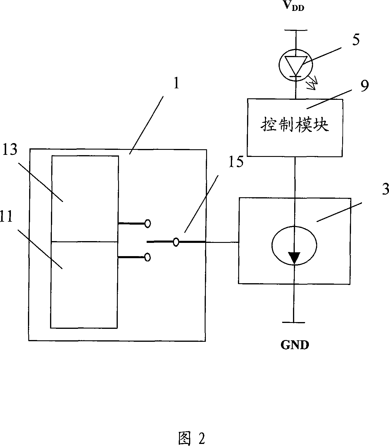
[0021] Please refer to FIG. 2 , which is a schematic structural diagram of the LED driving circuit of the present invention. The drive circuit includes a constant current bias module 1 , a constant current drive module 3 , a control module 9 and a light emitting diode 5 . The input end of the constant current drive module 3 is connected to the output end of the constant current bias module 1 , and the output end is connected to the light emitting diode 5 via the control module 9 . The anode of LED 5 is connected to the power supply V DD , the cathode is connected to the control module 9 to introduce current, so that the light emitting diode 5 emits light. The control module 9 controls the change of the current in the path between the constant current driving module 3 and the LED 5 . When the control module 9 controls the path current between the constant current driving module 3 and the LED 5 to be turned on, the constant current driving module 3 drives the LED 5 to light th...


PUM


Abstract

The invention comprises: a constant current biasing module and a constant current driving module. The constant current driving module is connected to a LED, and the constant biasing module is connected to the constant current driving module. Wherein, the constant current biasing module is used to generate two voltage sources with different voltages; the first voltage source is used to provide normal bias voltage for the constant current driving module; the second voltage source is used to provide a voltage lower than the normal voltage. In said circuit, there is a control module used for control the current variation between the constant current driving module and the LED.

Description

technical field [0001] The invention relates to a driving circuit, in particular to a light emitting diode driving circuit. Background technique [0002] In recent years, light-emitting diodes have the characteristics of small size, long life, energy saving, environmental protection and safety. They are increasingly popular as light sources in various lighting systems, especially in automotive lighting, public signs and signal sign building lighting, and outdoor large screens. Display and other fields have been widely used. [0003] Constant current source drive is the best way to drive LEDs. Driven by a constant current source, the current flowing on the light-emitting diode will not be affected by voltage changes, ambient temperature changes, and the discreteness of the light-emitting diode parameters, so that the current can be kept constant and various excellent characteristics of the light-emitting diodes can be fully utilized. [0004] With the development of technol...

Claims


Application Information

Patent Timeline
IPC IPC(8): H05B33/08H05B44/00
Inventor 卢晓冬赵一尘
Owner 苏州日月成科技有限公司
Learn More