Hot electric pressing cooking device used in kitchen
A cooking device and electric heating technology, applied in the direction of pressure cooker, etc., can solve the problems of parts processing, high difficulty in assembly, complex structure, low precision of pressure control, etc., and achieve high precision, reliable operation and low manufacturing cost.
- Summary
- Abstract
- Description
- Claims
- Application Information
AI Technical Summary
Problems solved by technology
Method used
Image

Examples
Embodiment 1
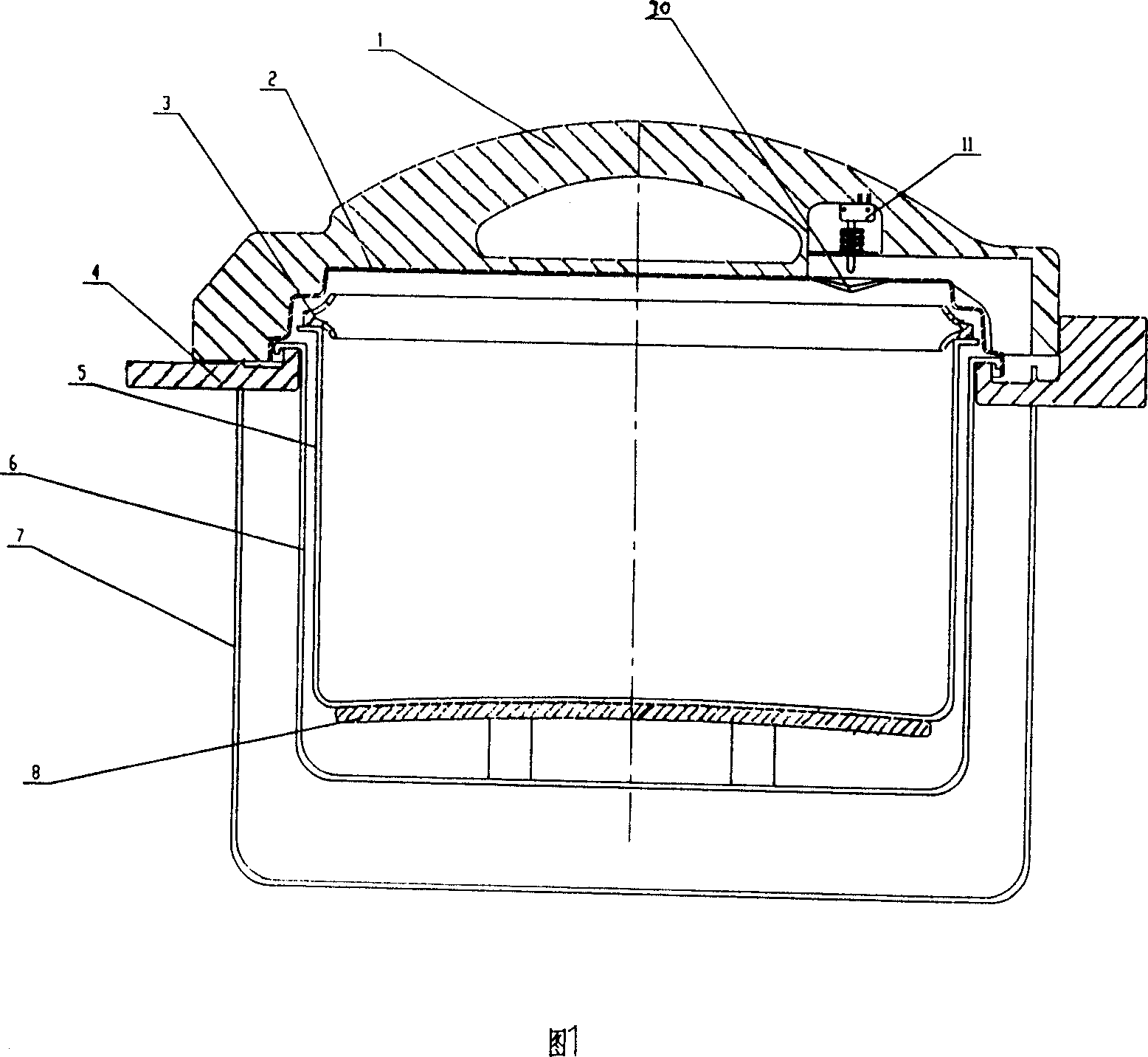
[0015] Embodiment 1: An electric heating pressure cooking device for kitchen, see accompanying drawing 1, including outer cover 1, inner cover 2, sealing ring 3, inner pot 5, outer shell 7, heating plate 8, pressure receiving plate 20, switch 11, control circuit etc. The pressure-receiving piece 20 described in this embodiment is an elastic diaphragm, which is installed on the inner cover 2 , and the switch 11 is installed on the outside of the inner cover 2 at a position corresponding to the pressure-receiving piece 20 .
[0016] Its working process is: when the pressure in the pot rises, the gas pressure pushes the pressure-receiving piece 20 to deform and make it protrude outward. When the pressure is high enough, the pressure-receiving piece 20 directly touches the switch 11. At this time, the control circuit controls the heating Disc 8 is powered off and stops heating. The pressure in the pot begins to decrease gradually. When the pressure in the pot drops to a certain l...
Embodiment 2
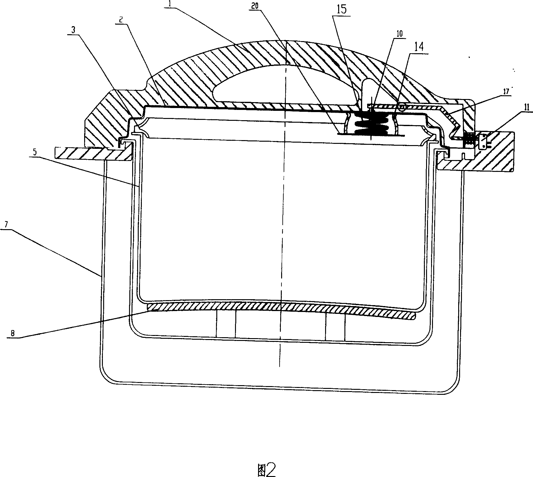
[0017] Embodiment 2: An electrothermal pressure cooking device for kitchen, see accompanying drawing 2, including outer cover 1, inner cover 2, sealing ring 3, inner pot 5, outer shell 7, heating plate 8, pressure receiving plate 20, switch 11, Lever 17, control circuit etc. are formed. The pressure-receiving piece 20 described in this embodiment is a rigid sheet, which is installed inside the inner cover 2 through an elastic sealing ring 14, and a thimble 10 is fixed on the outside of the pressure-receiving piece 20, and the upper end of the thimble 10 passes through the inner cover 2. A lever 17 is provided between the upper end of the thimble 10 and the switch 11 .
[0018] Its working process is: when the pressure in the pot rises, the gas pressure pushes the pressure-receiving piece 20 to move upward, compresses the elastic sealing ring 14, and at the same time drives the thimble 10 to move upward. When the pressure is high enough, the thimble 10 triggers the switch throu...
Embodiment 3
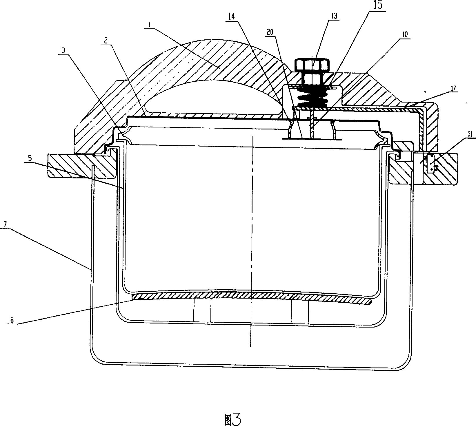
[0021] Embodiment 3: An electrothermal pressure cooking device for kitchen, see accompanying drawing 3, including an outer cover 1, an inner cover 2, a sealing ring 3, an inner pot 5, an outer shell 7, a heating plate 8, a pressure receiving plate 20, a switch 11, Lever 17, adjustment spring 15, control circuit etc. are formed. The pressure-receiving piece 20 described in this embodiment is a rigid sheet, which is installed inside the inner cover 2 through an elastic sealing ring 14, and a thimble 10 is fixed on the outside of the pressure-receiving piece 20, and the upper end of the thimble 10 passes through the inner cover 2. A lever 17 is provided between the upper end of the thimble 10 and the switch 11, and a pressure adjustment knob 13 is provided on the inside of the outer cover 1 at a position corresponding to the thimble 10 or the lever 17, and the pressure adjustment knob 13 is connected to the outer cover 1. The caps 1 are threadedly connected, and an adjustment spr...
PUM
 Abstract
Description
Claims
Application Information
 - R&D
- Intellectual Property
- Life Sciences
- Materials
- Tech Scout
- Unparalleled Data Quality
- Higher Quality Content
- 60% Fewer Hallucinations
Browse by: Latest US Patents, China's latest patents, Technical Efficacy Thesaurus, Application Domain, Technology Topic, Popular Technical Reports.
© 2025 PatSnap. All rights reserved.Legal|Privacy policy|Modern Slavery Act Transparency Statement|Sitemap|About US| Contact US: help@patsnap.com