Ultraviolet sterilizer with water port equipped at two ends of disinfection cavity

An ultraviolet ray and disinfection chamber technology, applied in the direction of light water/sewage treatment, discharge lamps, electrical components, etc., can solve the problems of low pressure tolerance of the disinfection chamber, reduce the disinfection effect, reduce the radiation dose, etc., to improve the disinfection effect, Increases UV radiation dose and reduces resistance

Active Publication Date: 2010-05-12
FUJIAN NEWLAND ENTECH CO LTD
View PDF3 Cites 0 Cited by
  • Summary
  • Abstract
  • Description
  • Claims
  • Application Information

AI Technical Summary

Problems solved by technology

[0002] From the current technology, the main cavity of the existing closed ultraviolet sterilizer is usually cylindrical, with a water inlet and outlet on the wall of the cylinder, and an ultraviolet lamp tube is installed at the end of the cylinder, and water flows into the cavity from the water inlet. The body flows out from the water outlet after being irradiated by ultraviolet rays. Since the water inlet and outlet are set on the wall of the cylinder, it is necessary to open on the wall of the cylinder, and then install the water inlet and outlet to connect with the water supply and water outlet pipes, and the water flows from the opening on the cylinder wall. When entering and exiting the cavity, the water flow pressure on the cylinder wall increases, and the water flows into the cavity from the water inlet and flows out from the water outlet after being irradiated by ultraviolet rays. Especially when dealing with large flow fluids, it is easy to cause a short circuit of the water flow, which shortens the distance of the water flow to be exposed to ultraviolet rays. , to reduce the dose of ultraviolet radiation on the water, reduce the disinfection effect, and there is a large difference in the head of the water inlet and outlet, the head loss of the water flow is too large, and the pressure of the disinfection chamber is small. Therefore, a method that can avoid short circuit of water flow and disinfection The cavity can withstand the ultraviolet disinfection device with high pressure and small head loss to meet the demand

Method used


Image

  • Ultraviolet sterilizer with water port equipped at two ends of disinfection cavity
  • Ultraviolet sterilizer with water port equipped at two ends of disinfection cavity
  • Ultraviolet sterilizer with water port equipped at two ends of disinfection cavity

Examples


Embodiment Construction

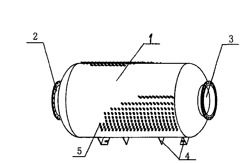
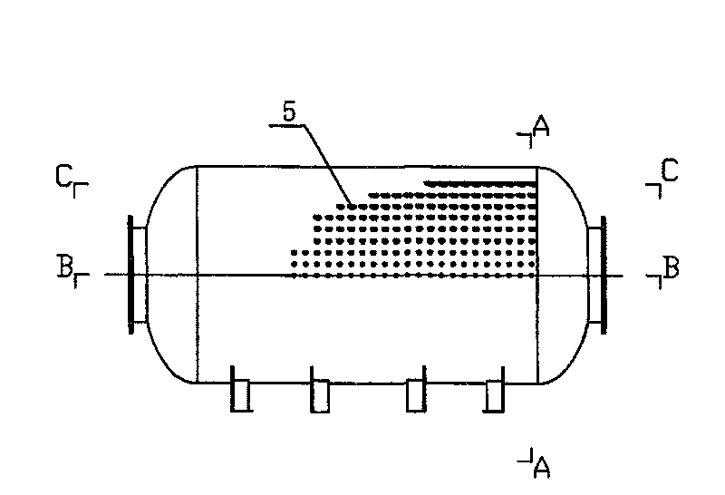
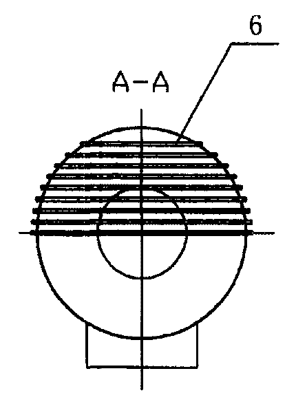
[0017] like Figure 1-5 As shown in , 1 is the ultraviolet disinfection chamber, 2 and 3 are the water outlets of the disinfection chamber, 4 is the foot of the disinfection chamber, 5 is the hole seat for the ultraviolet lamp tube, and 6 is the ultraviolet lamp tube.

[0018] The cavity 1 of the ultraviolet sterilizer is a cylinder with openings at both ends. The main cavity is cylindrical. The openings at both ends of the main cavity are used as two water outlets 2 and 3, which are respectively used as the water inlet and outlet of the sterilizer. Nozzle, set foot 4 under the cylinder of the sterilizer to support the ultraviolet sterilizer, and set a lamp tube mounting hole seat 5 at the intersection of a group of planes parallel to the cylinder axis section B-B in the cylinder and the cylinder wall for installing the ultraviolet lamp 6, that is, several ultraviolet lamp tubes are set on each plane parallel to the horizontal axis section, such as figure 2 , 3 , 4, two adj...


PUM


Abstract

This invention provides an ultraviolet radiation disinfection device, in which, its cavity is a drum with sealed surroundings and two opened ends, the main cavity is a drum and the two ends are set with two water gaps as the intake and outlet, lamp hole bases for mounting ultraviolet lamps are set at the cross of a set of planes with the wall of the drum parallel to the shaft section of the drum in it, namely, several branch lamps are set on the planes parallel to the shaft section, two adjacent planes parallel to the shaft sections are parallel to each other, and water enters into the cavityfrom the intake and is irradiated by the ultraviolet lamp to flow out from the outlet, lamps on a same plane parallel to the shaft section are parallel to each other and lamps on two adjacent planes parallel to the shaft section are not parallel.

Description

Technical field: [0001] The invention is an ultraviolet sterilizer. To be precise, it is an ultraviolet sterilizer with water outlets arranged at both ends of the disinfection chamber. Background technique: [0002] From the perspective of current technology, the main cavity of the existing closed ultraviolet sterilizer is usually cylindrical, with a water inlet and outlet on the wall of the cylinder, and an ultraviolet lamp tube is installed at the end of the cylinder, and water flows into the cavity from the water inlet. The body flows out from the water outlet after being irradiated by ultraviolet rays. Since the water inlet and outlet are set on the wall of the cylinder, it is necessary to open on the wall of the cylinder, and then install the water inlet and outlet to connect with the water supply and water outlet pipes, and the water flows from the opening on the cylinder wall. When entering and exiting the cavity, the water flow pressure on the wall of the cylinder i...

Claims


Application Information

Patent Timeline
Patent Type & Authority Patents(China)
IPC IPC(8): C02F1/32H01J61/00A61L2/10
Inventor 陈健吴志军姚向阳
Owner FUJIAN NEWLAND ENTECH CO LTD
Why Eureka
Try Eureka