Method for determining pump flow without the use of traditional sensors

A pump flow, agitator technology, applied in the field of pump systems, that can solve problems such as reducing flexibility, increasing drive system cost and complexity, and adding failure point costs.

Active Publication Date: 2007-09-12
ITT MFG ENTERPRISES LLC
View PDF5 Cites 15 Cited by
  • Summary
  • Abstract
  • Description
  • Claims
  • Application Information

AI Technical Summary

Problems solved by technology

However, this technique requires the use of auxiliary gauges, which increases the cost and complexity of the drive system, and adds possible points of failure and unnecessary cost
It also utilizes flow versus TDH curves calibrated at several dedicated speeds, thus reducing flexibility during field setup

Method used


Image

  • Method for determining pump flow without the use of traditional sensors
  • Method for determining pump flow without the use of traditional sensors
  • Method for determining pump flow without the use of traditional sensors

Examples


Embodiment Construction

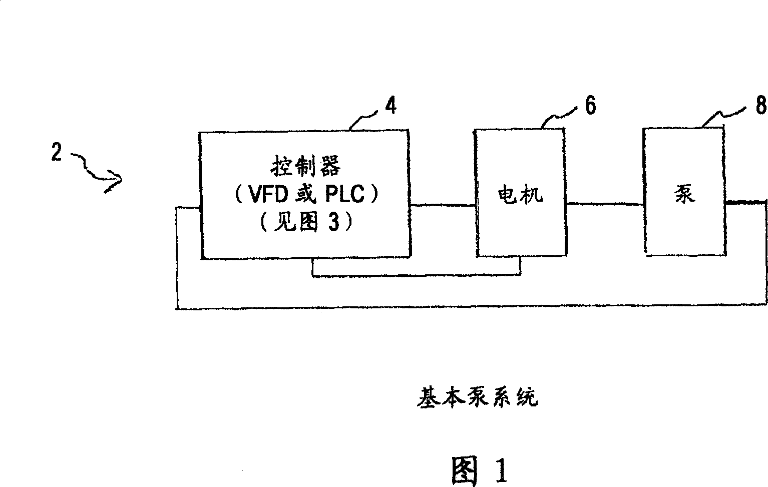
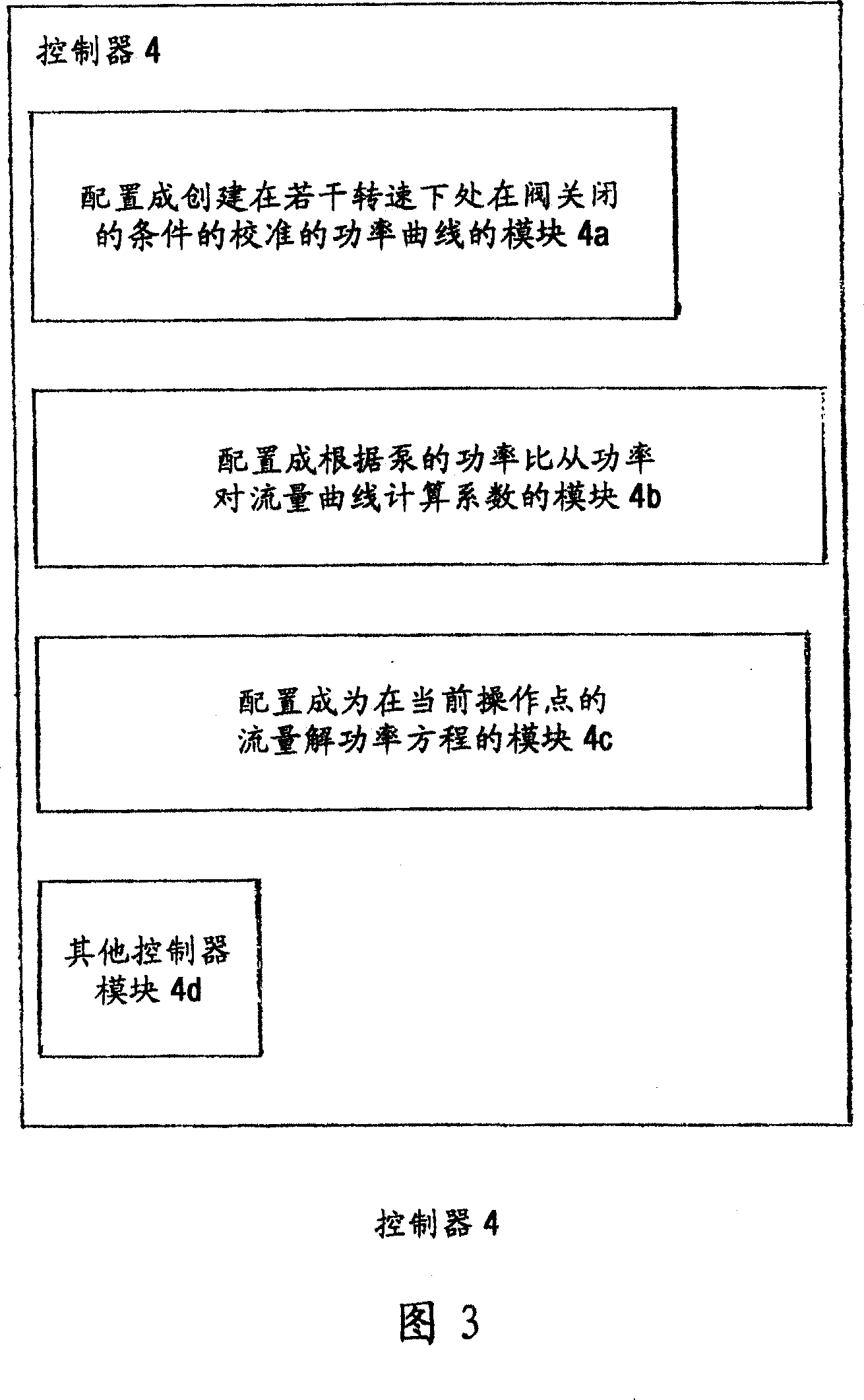
[0036] FIG. 1 shows a basic pump system according to the invention, generally indicated at 2 , with a controller 4 , a motor 6 and a pump 8 . In operation, according to the present invention, the controller 4 is used to determine pump flow without the use of conventional sensors based on a technique consistent with that shown and described herein, wherein the technique creates Calibrate the power curve at the valve closed condition; calculate coefficients from the power versus flow curve based on the power ratio of the pump; and solve the power equation for the flow at the current operating point.

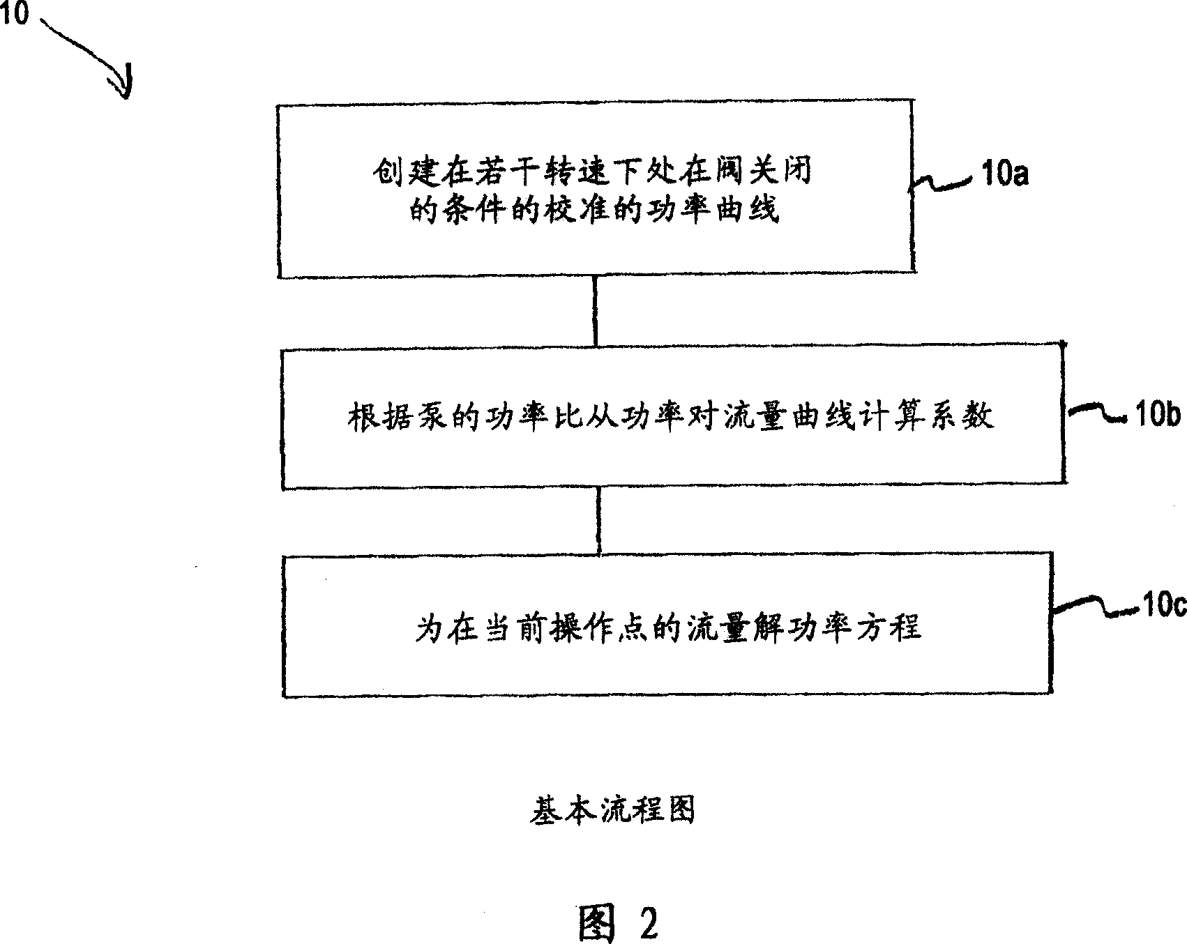
[0037]Figure 2 shows by way of example a flow chart generally indicated at 10 with the basic steps 10a, 10b, 10c of a pump flow determination algorithm that can be implemented by the controller 4 according to the invention. The determined flow value can also be used as an input to a PID control loop to control the flow without the need for an external flow meter or traditional meas...


PUM


Abstract

A technique for determining pump flow without using traditional sensors features steps and modules for creating a calibrated power curve at closed valve conditions at several speeds; calculating coefficients from a normalized power curve based on a pump's power ratio; and solving a polynomial power equation for flow at the current operating point. The calibrated power curve may be created by increasing the speed of the pump from a minimum speed to a maximum speed and operating the pump with a closed discharge valve. This data is used to correct published performance for shutoff power and best efficiency point power at rated speed in order to determine the pump's power ratio. It is also used to accurately determine closed valve power at the current operating speed. The pump's power ratio is determined by the equation: Pratio=Pshutoff @100%/PBEP<SUB2>-</SUB2>corr. The polynomial power equation may, for example, include a 3rd order polynomial equation developed using coefficients from the normalized power versus flow curve, and corrections may be made for speed, hydraulic efficiency and specific gravity in the polynomial power equation.

Description

[0001] Cross References to Related Applications [0002] This patent application claims to enjoy the rights and interests of provisional patent application No. 60 / 780,546 entitled "Method for Determining Pump Flow Without the Use of Traditional Sensors" (911-2.24-1 / 05GI003) submitted on March 8, 2006. This patent Application is also related to Patent Application No. 11 / 601,373 entitled "Method and Apparatus For Pump Protection Without the Use of Traditional Sensors" (911-2.22-1 / 05GI002), filed on November 17, 2006, and also related to Provisional patent application No. 60 / 780,547 entitled "Method for Optimizing ValvePosition and Pump Speed ​​in a PID Control Valve System without the Use of External Sensors)" (911-2.23-1 / 06GI001) submitted on the 8th. The entire contents of all of these patent applications are hereby incorporated by reference. technical field [0003] The present invention relates to pump systems having pumps including centrifugal pumps; and in particular to m...

Claims


Application Information

Patent Timeline
Patent Type & Authority Applications(China)
IPC IPC(8): F04D15/00G01F1/00
CPCF04D15/0088F04D27/0261F04D27/001F04D15/0066F04D27/004F05D2270/335Y02B30/70G01F1/00
Inventor 丹尼尔·J·克南尤金·P·萨比尼尼古拉斯·W·甘宗安东尼·E·斯塔瓦莱
Owner ITT MFG ENTERPRISES LLC
Why Eureka
Try Eureka