Total station instrument combined location method based on optical fiber gyro

A fiber optic gyroscope and total station technology, applied in directions such as rotating gyroscopes, can solve the problems of low impact resistance and power consumption, and achieve the effects of simple hardware installation requirements, simple operation process and small size

Inactive Publication Date: 2007-09-12
SOUTHEAST UNIV
View PDF2 Cites 14 Cited by
  • Summary
  • Abstract
  • Description
  • Claims
  • Application Information

AI Technical Summary

Benefits of technology

The technical effect of this patented technology for an Optical Fiber Gyroscopic Total Station (FTG) combining orientational methods involves simplifying its construction without requiring any special equipment or tools at both ends. It allows users to install these devices while still being able to accurately determine their position with respect to another object called thetotal station. Additionally, the new design uses smaller and lighter components than traditional mechanisms like electromechanics, which makes them more reliable but less resistant against external shocks compared to older designs such as electrostatic MEMS). Overall, this innovation improves overall performance and efficiency in measuring angles.

Problems solved by technology

This technical problem addressed in this patents relates to improving the efficiency and accuracy of automatically oriented systems (ATS) without requiring cumbersome manual adjustment processes such as alignment and calibration devices. Current methods require bulky hardware components like goniometers and guiding lines attached to the machine frame, making them hard to install accurately due to their size and complexity.

Method used


Image

  • Total station instrument combined location method based on optical fiber gyro
  • Total station instrument combined location method based on optical fiber gyro
  • Total station instrument combined location method based on optical fiber gyro

Examples


Embodiment Construction

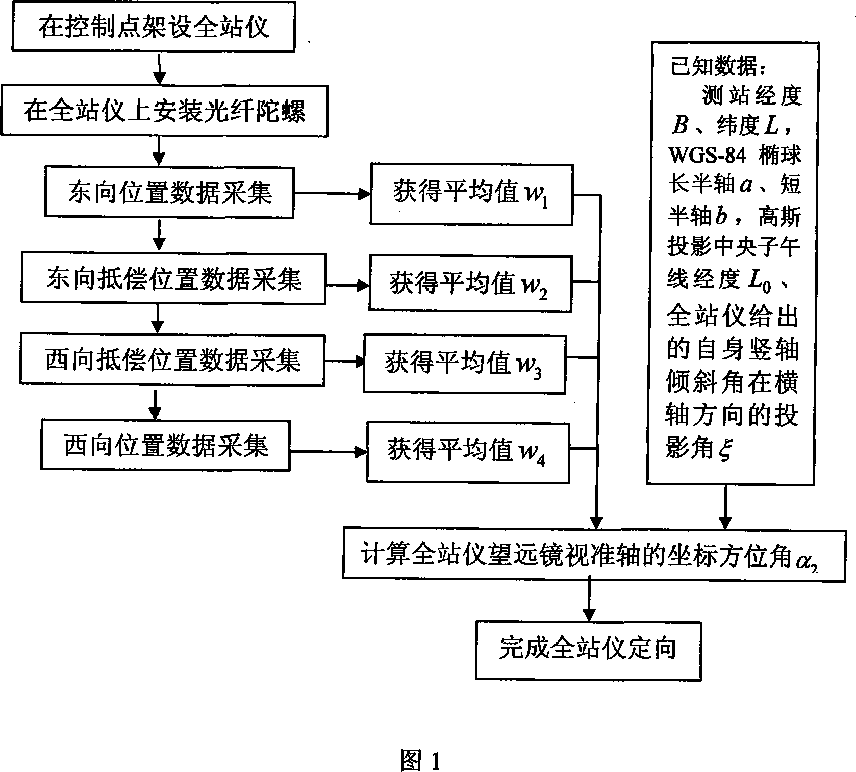
[0026] Below in conjunction with accompanying drawing and embodiment the present invention is further described:

[0027] Fig. 1 is a technical flow chart of the combined orientation method of the total station based on the fiber optic gyroscope, which includes seven operation steps. A specific embodiment of the application of the present invention is to carry out total station orientation on control point A when carrying out cadastral surveying and mapping in Xuanwu District, Nanjing. Control point A is in a residential area surrounded by buildings. According to the traditional total station orientation method, a control point B for orientation needs to be arranged at a distance of 200 meters from control point A. This is very difficult. Utilizing the present invention can complete the orientation of the total station without distributing the control point B. In this embodiment, the ZD-75 fiber optic gyro developed by Zhejiang University with a zero bias stability of 0.2 deg...


PUM


Abstract

This invention relates to a kind of fiber-optic gyro based, full station instrument combination orientation mode, and applies to plotting work. In plotting scene, the invention connects fiber-optic gyro(1) with full station instrument telescope(3) by adaptor(2), and make optical fibre gyro can follow full station instrument telescope simultaneously do 180 degree turning reel full station instrument cross shaft, respectively on two horizontal positions of east and west direction of gyro axis that differ by 180 degree; each horizontal position process 2 x 2 position gyro data acquisition on full station instrument perpendicular tray that differ by 180 degree; using formula to count out full station instrument collimation axis true azimuth, survey station meridian convergence angle, then can obtain full station instrument collimation axis grid azimuth, realize full station instrument orient. The invention structure is simple, not need to process alignment error calibration, just simple operation can realize full station instrument orient on only one control point situation. The invention can be used for town, forest, and mountainous area such on distressed area's plotting work.

Description


Claims


Application Information

Patent Timeline
Owner SOUTHEAST UNIV
Why Eureka
Try Eureka