System for determining RF path loss between an RF source and an RF receiver with hysteresis and related methods

A path loss and receiver technology, applied in the field of communication systems, can solve a lot of time problems

Active Publication Date: 2007-09-12
RES IN MOTION LTD
View PDF1 Cites 2 Cited by
  • Summary
  • Abstract
  • Description
  • Claims
  • Application Information

AI Technical Summary

Problems solved by technology

In order to scan every channel of a GAM mobile phone, phones using traditional, semi-intuitive methods require a lot of time

Method used


Image

  • System for determining RF path loss between an RF source and an RF receiver with hysteresis and related methods
  • System for determining RF path loss between an RF source and an RF receiver with hysteresis and related methods
  • System for determining RF path loss between an RF source and an RF receiver with hysteresis and related methods

Examples


Embodiment Construction

[0018] The present invention will now be described more fully hereinafter with reference to the accompanying drawings, in which preferred embodiments of the invention are shown. However, this invention may be embodied in many different forms and should not be construed as limited to the embodiments set forth herein. Rather, these embodiments are provided so that this disclosure will be thorough and complete, and will fully convey the scope of the invention to those skilled in the art. Throughout, like numbers refer to like elements, and primes are used to indicate like elements in alternative embodiments.

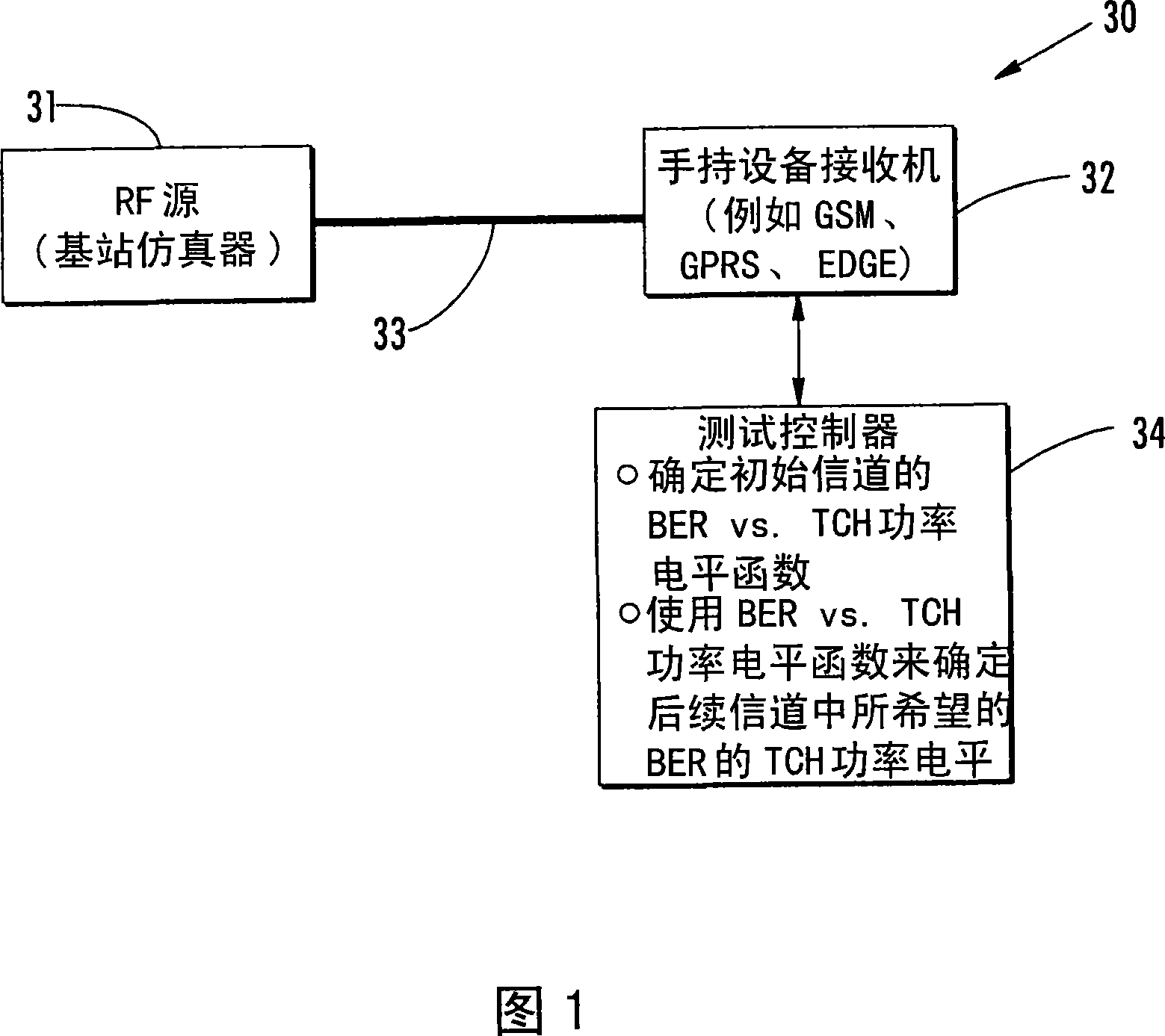
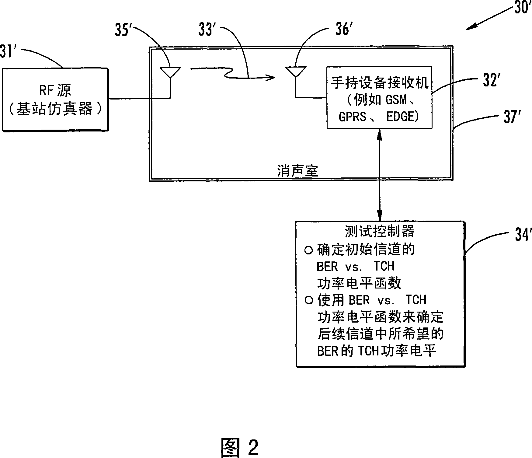
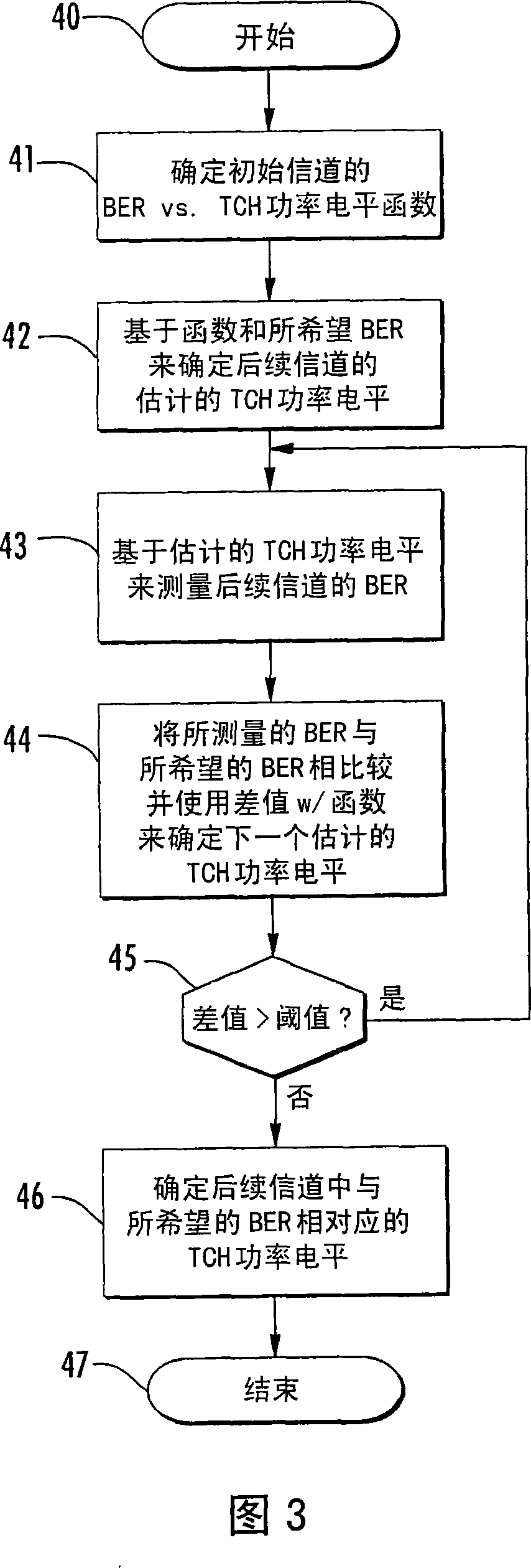
[0019] A test method for determining radio frequency (RF) path loss between an RF source and an RF receiver for a given RF channel in a given RF frequency band will first be generally outlined, and more detail will be provided below. An RF source may transmit RF power values ​​at relatively fine intervals, an RF receiver may generate Received Signal Strength Indicator (RSS...


PUM


Abstract

A test method is for determining RF path loss between an RF source and an RF receiver. The RF source may transmit RF power values at a relatively fine granularity, and the RF receiver may generate RSSI values at a relatively coarse granularity and have an unknown hysteresis about each transition between adjacent RSSI values. Hysteresis edges may be determined about a given RSSI value transition at the RF receiver by sweeping RF power values transmitted from the RF source in increasing and decreasing directions. A relationship between the relatively fine granularity RF power values and the relative coarse granularity RSSI values may be determined using the hysteresis transition edges. The RF path loss for a given channel may be determined based upon a given RSSI at a given RF power value and the relationship between the relatively fine granularity RF power values and the relative coarse granularity RSSI values.

Description

technical field [0001] The present invention relates to the field of communication systems, and more particularly to performance testing and related methods in mobile wireless communication systems, such as cellular communication systems. Background technique [0002] In cellular communications equipment, radio sensitivity is the fundamental number that describes the performance of a radio receiver. Conducted (ie, through RF cables) and radiated (ie, through wireless communication links) radio sensitivity measurements are frequently performed during radio design, certification, and verification. These measurements were performed by reducing the base station power transmit level until the receiver's residual bit error rate (RBER) reached the desired level (specifically 2.44%). [0003] For example, for Global System for Mobile Communications (GSM) mobile devices, there are multiple communication frequency bands, each ranging from at least one hundred channels to nearly four ...

Claims


Application Information

Patent Timeline
Patent Type & Authority Applications(China)
IPC IPC(8): H04B7/005H04B1/707H04Q7/34
CPCH04B17/309H04B17/008H04B17/29H04B17/0042H04B1/38H04B1/62
Inventor 齐亦红佩里·贾穆斯伍斯基迈克尔·舍滕恩
Owner RES IN MOTION LTD
Why Eureka
Try Eureka