Vehicle front body structure

A technology for the front part of the body and the tower part, which is applied to the superstructure, superstructure sub-assemblies, vehicle parts, etc., can solve the problem that the collision energy cannot be fully dispersed and transmitted.

Inactive Publication Date: 2007-09-19
MAZDA MOTOR CORP
View PDF1 Cites 55 Cited by
  • Summary
  • Abstract
  • Description
  • Claims
  • Application Information

AI Technical Summary

Problems solved by technology

However, with this structure, the collision energy may not be sufficiently dispersed and transmitted to the upper part of the vehicle body

Method used


Image

  • Vehicle front body structure
  • Vehicle front body structure
  • Vehicle front body structure

Examples


no. 1 approach

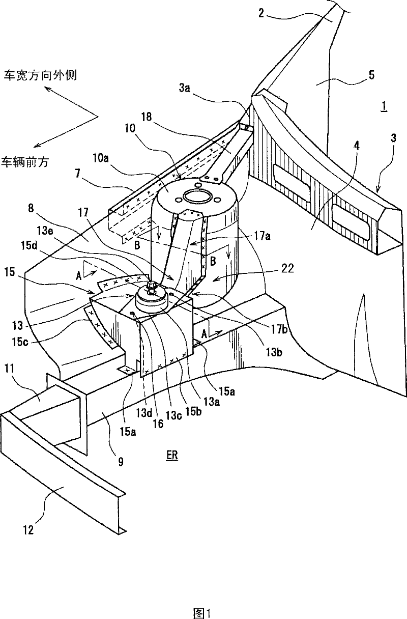
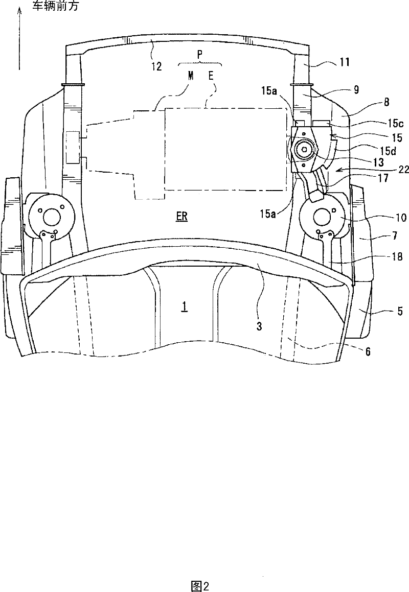
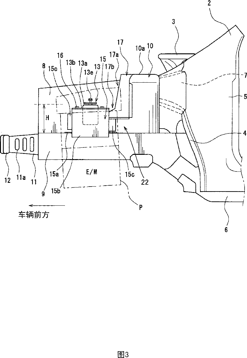
[0052] 1 and 3 are a perspective view and a side view, respectively, showing a main part (right side portion) of a vehicle body front structure according to a first embodiment of the present invention, and FIG. 2 is a plan view of the vehicle body front structure. In FIGS. 1 to 3 , the front part of the compartment 1 mainly includes a pair of A-pillars (also known as A-pillars) located at the lower edge of the front glass (not shown) and connecting the left and right pairs in the vehicle width direction. A neck portion 3 of a window pillar or front pillar 2; a dash panel 4 as a partition separating the vehicle compartment 1 and the engine room ER; a hinge support tower extending downward from the A-pillar 2 (hinge tower) 5.

[0053] The dash panel 4 is arranged at the lower part of the vehicle neck 3 , and its left and right side edges are respectively connected to a pair of left and right hinge support towers 5 . The hinge support tower 5 is provided with door hinges for fre...

no. 2 approach

[0099] In the above-mentioned first embodiment, the installation part 15 and the gusset member 17 are provided, and the retreat energy of the power plant P is distributed and transmitted to the upper part 10a of the suspension support tower 10 through them, but it is not necessarily limited thereto. For example, in the present invention, it is also possible to replace the mounting part 15 and the gusset part 17 of the engine assembly part, and set a single part (gusset part 117) having both functions as shown in Figure 9, and use the gusset part 117 constitutes the frame member 22 .

[0100]Fig. 9 is a perspective view showing the main parts of the vehicle body front structure related to the second embodiment, Fig. 10 is an exploded perspective view showing the main parts of the car body front structure related to the second embodiment, Fig. 11(a), 11 (b) are respectively the sectional view in the direction of the arrow of line C-C and the sectional view in the direction of th...

no. 3 approach

[0117] Next, the configuration of the third embodiment will be described with reference to FIGS. 12 to 18 . 12 is a right side perspective view showing a left side portion of a vehicle body front structure according to the third embodiment, FIG. 13 is a left side perspective view showing a right side portion of the vehicle body front structure, and FIG. 14 is a vehicle body front structure. Figure 15 is a top view of the front structure of the vehicle body, Figure 16 is a front view of the left part of the front structure of the vehicle body, and Figure 17 is a view of the front structure of the vehicle body viewed from the inside of the engine room The side view of the left part, Fig. 18 (a) is a sectional view of the E-E line arrow direction in Fig. 16, and Fig. 18 (b) is a sectional view of the F-F line arrow direction in Fig. 16 . In each figure, the left side of the driver is referred to as the left side of the vehicle, and the right side of the driver is referred to as t...


PUM


Abstract

The present inventive vehicle front body structure, comprises a front side frame provided so as to project forward from a dash panel; an apron member provided so as to project substantially forward at a location that is outside the vehicle width direction of the front side frame; a suspension tower portion provided so as to at least partly protrude in an engine room for at least partly accommodating a front suspension vibration damper therein, the suspension tower portion being engaged with the apron member and the front side frame; an engine mount provided at the front side frame in front of the suspension tower portion so as to support a side portion of a power plant; and a first connecting member provided so as to straightly interconnect an upper portion of the suspension tower portion and a portion of the front side frame that is located in front of the engine mount, the member being disposed so as to overlap with the engine mount in a top view. The present invention provide a front structure of vehicle body for transmitting a collision load working on a front side frame to an upper portion of a vehicle body which is capable of absorbing the energy caused by the axial compression of the front side frame by suppressing any upward bend of the front side frame by reliably dispersing the collision load to the upper portion of the vehicle body while arranging an engine mount on the front side frame.

Description

technical field [0001] The present invention relates to a vehicle body front structure, in particular to a vehicle body front structure including a pair of left and right front sideframes and a suspension tower for mounting a suspension device. Background technique [0002] In the past, with regard to the front body structure of automobiles, the issue of how to improve the collision safety performance of the vehicle and how to distribute and transmit the collision load acting on the front side members extending in the front-rear direction of the vehicle body to the rear side of the vehicle body has been studied. [0003] In the conventional automobile front body structure, the above-mentioned collision load is mainly transmitted to the body frame (body frame) connected to the rear end of the front side member and located at the lower part of the vehicle body rather than to the upper part of the vehicle body. Therefore, the front side member has Th...

Claims


Application Information

Patent Timeline
Patent Type & Authority Applications(China)
IPC IPC(8): B62D25/16
CPCB62D25/088
Inventor 佐佐木伸井上实青沼隆浩藤井宏章
Owner MAZDA MOTOR CORP
Why Eureka
Try Eureka