Electric lockset structural

A kind of lock structure and electronic technology, applied in the application of electric locks, building locks, locks, etc., can solve the problems of power failure, deformation, mechanical displacement, etc., and achieve the effect of simple and reasonable mechanism and convenient use

Inactive Publication Date: 2007-09-19
王俭
View PDF0 Cites 19 Cited by
  • Summary
  • Abstract
  • Description
  • Claims
  • Application Information

AI Technical Summary

Problems solved by technology

The electric control principle of handle unlocking is to electrically control the lifting and shrinking of a bolt, which can block the handle rotation shaft, allowing or prohibiting the handle rotation; the motor automatic unlocking is that the motor drives the lock bolt to open and close. The disadvantages of these two methods are: 1. The inside of the lock body needs a power supply, so the volume is not small, and there is also the threat of power failure; 2. The electronically controlled actuator (electrically controlled bolt, electronically controlled lock bolt) can be subjected to external forces in the non-driving direction, and mechanical displacement, Deformation leads to failure of electronic control

Method used


Image

  • Electric lockset structural
  • Electric lockset structural
  • Electric lockset structural

Examples


Embodiment 1

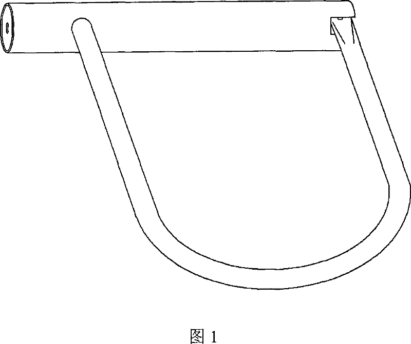
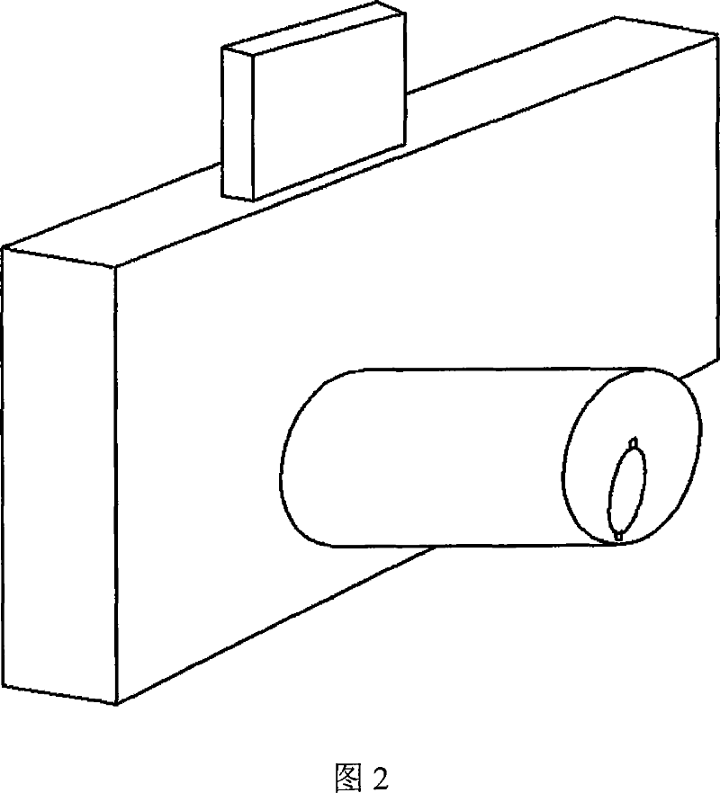
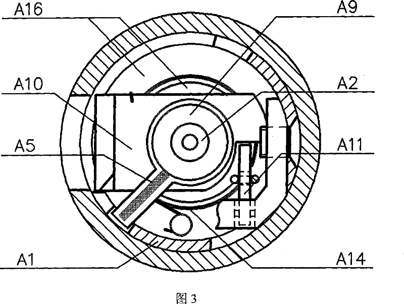
[0029] Fig. 3, Fig. 4 are a kind of U-shaped electronic padlock mechanism diagram made by the present invention. U-shaped electronic padlock is composed of lock ring rod, lock body steel pipe and lock cylinder assembly, lock cylinder assembly includes lock head, lock head rotating core A4 , Turn the lock tongue A10, the electrode mandrel A2, the electrode reed A6, the electrode circuit board A5, the stopper block A11, the solenoid valve A12 and the electric control circuit board. On A1, the lock tongue A10 is rotated and fixed on the lock head rotor A4. When the key is inserted into the lock head, the metal retainer of the key, the lock head and the lock body are connected together to form the circuit ground, and the elastic electrode contact 29 on the key is connected to the lock head. The electrode mandrel A2 on the head rotating core touches, the electrode rod is insulated through the bottom plate of the lock tongue A10, and is pressed against the electrode of the circuit bo...

Embodiment 2

[0032] Figure 10 and Figure 11 are the mechanism diagrams of the electronic door lock of the filing cabinet made of the present invention. The electronic door lock of the filing cabinet is mainly composed of a lock head, a lock head rotating core B4, a pick B7, a toggle ring B8, a lock tongue B10, an electrode core Rod B2, electrode circuit board B5, electrode reed B6, stopper block B11, solenoid valve B12 and electronic control circuit board B13, the paddle B7 is fixed on the lock head rotor B4, when the key is inserted into the lock head, the The metal retainer is connected with the lock head and the lock body to form the circuit ground. The elastic electrode contact 29 on the key is in contact with the electrode mandrel B2 in the lock head rotor, and the tail of the electrode rod is insulated through the pick B7 and fixed in the circuit. The board B5 is connected to the electrode on the circuit board, and then presses into the electrode of the electronic control circuit boar...

Embodiment 3

[0034] Fig. 12 and Fig. 14 are schematic diagrams of the common electronic door lock mechanism made by the present invention. The common electronic door lock is mainly composed of a lock head, a lock head rotating core C4, a rotating core positioning pin, a T-shaped lever C18, and a toggle ring C8 , lock body assembly, electrode mandrel C2, metal ring electrode C19, elastic electrode contact C21, electrode circuit board C5, block block C11, solenoid valve C12 and electric control circuit board, clamped at the tail of the lock head rotor C4 Holding the T-shaped driving lever C18, a toggle ring C8 is arranged on the lock body cover plate, and the T-shaped driving lever C18 is inserted in a rectangular hole of the toggle circle C8, and the toggle circle C8 can be rotated. When the key is inserted into the lock head, the metal retainer of the key, the lock head and the lock body are connected together to become the circuit ground, and the elastic electrode contact 29 on the key tou...


PUM


Abstract

An electronic lockset structure comprised of key, lock head, lock body, electrical control circuit and key manager. Characterized in that the key is provided with built-in battery and electronic cipher circuit, electrode contactor on the key elastically contacts with electrode contactor provided inside the lock head, and the circuit is linked to the electrical control circuit in the lock body, the electrical control circuit inside the lock starts working, electrically controlled microprocessor decodes and drives the treatment, if cipher fits, the magnetic valve will be attraction-closed and the block is driven to move away with micropower, drawing tooth or groove on the key activates lock bolt in the lock to move, unlocking is accomplished. There is no electric source inside the lock body, and the inserted key supplies power. The key is molding standardly, which is generally serviced with the lock. One key is capable of unlocking a plurality of electronic locks, and one electronic lock can be fitted with multiple keys. The lockset structure of the invention is mature and ingenious, electronic cipher is employed, particularly that electrical micropower driving and key standardization technology are employed, which is simple and reasonable, and is easy to use, it is safe and reliable.

Description

Technical field [0001] The invention relates to a microelectronic-controlled lock mechanism, in particular to an electronic lock which adopts software electronic password technology and standardized key and its microcomputer management. Background technique [0002] The mechanical lock has been improved and perfected for thousands of years, and its structure is simple and compact, ingenious and reasonable. Since she is a purely mechanical mechanism, there are still defects that the mechanical code can be cracked and opened illegally. [0003] At present, the known electronic locks in the world are basically electronic door locks, safe locks and car door locks, and electronic padlocks and small electronic door locks for file cabinets have not yet appeared. The electronic locks in the world have basically abandoned the mechanical key that played an ingenious role in the original mechanical lock, and divided her function into two: the password decryption is performed by the ke...

Claims


Application Information

Patent Timeline
Patent Type & Authority Applications(China)
IPC IPC(8): E05B49/00
Inventor 王俭
Owner 王俭
Why Eureka
Try Eureka