Multifunction safety knife switch

A safety gate and multi-functional technology, which is applied in the field of multi-functional safety switch blades, can solve the problems of no safety locking mechanism and potential safety hazards.

Inactive Publication Date: 2007-09-19
郭胜利 +1
View PDF0 Cites 6 Cited by
  • Summary
  • Abstract
  • Description
  • Claims
  • Application Information

AI Technical Summary

Problems solved by technology

At the same time, there is no safety locking mechanism for any type of existing switch knife, and its opening or closing method is arbitrary, that is, anyone can open and close a certain switch knife and switch at any time without any restriction
In this way, there are certain potential safety hazards during use, especially during maintenance, accidents often occur due to accidental closing.

Method used


Image

  • Multifunction safety knife switch
  • Multifunction safety knife switch
  • Multifunction safety knife switch

Examples


Embodiment 1

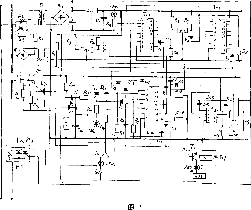
[0026] As shown in Figure 1: This embodiment consists of a power supply system circuit, a zero-crossing pulse sampling circuit, an on-off instruction recognition and control circuit, a variety of protection function circuits, a counting control circuit and arc suppression, an operation control circuit and a shutdown control circuit. circuit and inspection lock circuit.

[0027] The power supply system circuit consists of B, Q 1 、C 1 , IC 1 、C 2 ,LED 1 , RH form the power supply circuit of the whole machine. The alternating current is stepped down by the transformer B and passed through the full bridge Q 1 Complete the full-wave rectification process, output DC voltage, through C 1 Filtered and sent to IC 1 The stable voltage output stable DC power supply (+6V) is sent to each circuit. IC 1 It is a three-terminal regulator integrated circuit, LED 1 The luminous tube indicates the working status of the power supply system.

[0028] The zero-crossing pulse sampling cir...

Embodiment 2

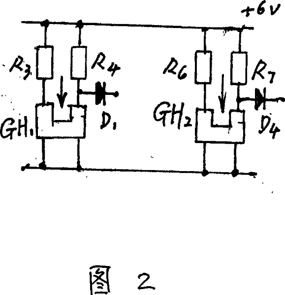
[0039] In this embodiment, on the basis of the structure of Embodiment 1, the identification mode of the opening and closing command identification and the control circuit is designed as an infrared light control mode, as shown in Figure 2: it uses a concave infrared optical coupling device GH 1 、GH 2 As an identification element, when the barrier is inserted into the groove, D 1 、D 4 Output high potential respectively; when there is no obstacle in the groove, D 1 、D 4 Output low potential respectively. This embodiment is to use the blocking of infrared light to control GH 1 、GH 2 The output potential of the switch to control the opening and closing of the knife. GH 1 It is the opening control, and the GH needs to be pulled out when the knife is turned off. 1 The barrier in the groove makes D 1 Potential changes from high to low, IC 2 Pin 11 of the pin becomes low level at the same time, thereby releasing the IC 2 In the locked state, the zero-crossing pulse is sent...

Embodiment 3

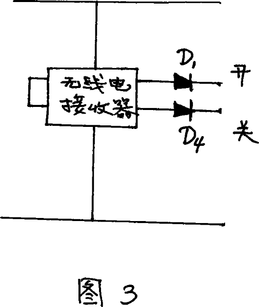
[0042] In this embodiment, on the basis of the structure of Embodiment 1, the identification mode of its on-off command identification and control circuit is designed as a radio wave control mode, as shown in Figure 3: it uses a radio transmitter and a receiver as identification Components to control the opening and closing of the knife. When the switch knife is turned on, the radio wave sent by the radio transmitter makes the radio receiver send a command signal to make D 1 Potential changes from high to low, IC 2 Pin 11 of the pin becomes low level at the same time, thereby releasing the IC 2 In the locked state, the zero-crossing pulse is sent to the IC 2 The 10 pins enable the IC 2 Start counting, when the count reaches the set value, IC 2 Pin 2 outputs a high level pulse to the IC 4 1 pin, its 4 pin output high level makes T 2 Turn on GY 2 Work. closed KS 2 、KS 3 control pole. Make KS 2 、KS 3 Conducting the AC power output to the load to complete the start of...


PUM


Abstract

The invention discloses a multifunctional safe guillotine which mainly comprises following circuits, opening and closing of the guillotine are identified by an opening and closing instruction and controlled by a control circuit so that opening and closing manners of the guillotine are restriction mode control. A zero-past pulse instruction signal is obtained by a zero-past sampling circuit, thereby an impact phenomenon of voltage and current is not generated on the circuit when the guillotine is opened or closed, and the instruction signal provides a count time for work time sequence of an arc suppression circuit and an operation circuit; an automatic switch between a contactless work mode and a contact work mode is timely done by a count control circuit, the arc suppression, operation circuits and a closing control circuit, so that the guillotine is in the contactless work mode when turning on and turning off power source to avoid generation of an impact phenomenon of electric arc and current; the guillotine is in the contact work mode when being in normal operation, thereby solving a problem of temperature increase during operation process. A safe locking function and a plurality of protection functions further increase safety and reliability for the usage of the guillotine.

Description

technical field [0001] The invention belongs to the technical field of switch blades, and mainly relates to a multifunctional safety switch blade. Background technique [0002] As we all know, the devices that complete the task of turning on or off the load and the power supply in each link of power use are called "switches", "switches" and "circuit breakers", which are crucial components of power use. From the perspective of electricity theory: the function of "knife switch, switch and circuit breaker" is the start and end of electric energy conversion, so it is one of the key equipment with wide application in all links of electric power conversion. However, although there are various types of "switches and circuit breakers" (hereinafter collectively referred to as "switch blades") sold in the market, their structural components all belong to the "mechanical contact" type. That is, the way of turning on or off the power supply and the load is the opening and closing and s...

Claims


Application Information

Patent Timeline
Patent Type & Authority Applications(China)
IPC IPC(8): H01H9/56H02H3/08H02H3/20H02H3/24H02H5/04H01H9/54H01H36/00H03K17/94
Inventor 郭胜利吉学庆
Owner 郭胜利
Why Eureka
Try Eureka