

Treatment instrument for coronary artery bypass operation
A technology of coronary arteries and suction cups, applied in the field of coronary artery bypass grafting devices, can solve problems such as deviation and falling off, and achieve the effect of preventing damage, little possibility of heart deviation or falling off, and good followability
- Summary
- Abstract
- Description
- Claims
- Application Information
AI Technical Summary
Problems solved by technology
Method used
Image

Examples
no. 1 example
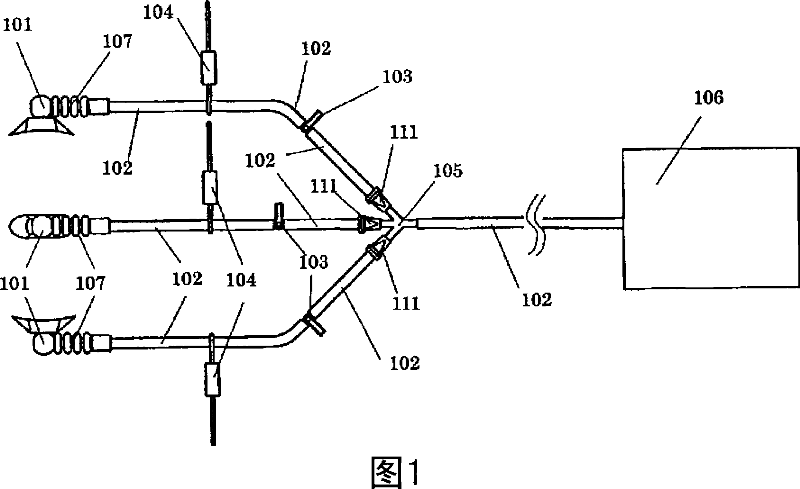
[0055] FIG. 1 is a diagram showing an example of a coronary artery bypass grafting device of the present invention. The coronary artery bypass grafting device shown in FIG. 1 has a plurality of adsorption members, preferably greater than or equal to three. FIG. 1 illustrates a configuration provided with three adsorption members.
[0056] The adsorption member includes a flexible tube 102, a suction cup portion 101 provided on the end side of the flexible tube 102, a three-way cock 103 as a switch member provided on the flexible tube 102, a holding member 104 for holding the flexible tube 102, and a three-way cock 103 as a switch member provided on the flexible tube 102, and 102 duckbill valve 111 on check valve. Here, FIG. 1 exemplifies a configuration in which all three adsorption members include the respective duckbill valves 111 , but at least one of the plurality of adsorption members may include the duckbill valve 111 .
[0057] In the coronary artery bypass grafting d...
no. 2 example
[0110] In the coronary artery bypass grafting apparatus according to the first embodiment, the suction cup portion 101 may be composed of at least two or more approximately circular suction cups. Since the suction cup portion 101 has at least two or more nearly circular suction cups, the device is better in tracking ability during suction to the curved surface of the heart wall surface as well as to the generally flat portion, thereby being well suited for use in High precision keeps the heart in the predetermined position. Furthermore, adsorption to the heart wall surface can be achieved over the largest possible contact area without aspirating the blood vessel. The difference between this embodiment and the first embodiment will be described in more detail below mainly referring to FIG. 6 , (a) to (e) in FIG. 7 and FIG. 8 .
[0111] Fig. 6 shows an example of a coronary artery bypass graft device according to the present invention. The coronary artery bypass graft device s...
no. 3 example
[0126] In the coronary artery bypass grafting apparatus according to the above-described embodiments, the adsorption member may further include an auxiliary member for disposing the suction cup portion at a predetermined position of the object to be adsorbed. A case of using the coronary artery bypass grafting apparatus according to the first embodiment will be described below with reference to FIGS. 9 and 10 .
[0127] Fig. 9 is a schematic diagram showing the configuration of the coronary artery bypass grafting device according to the present embodiment. FIG. 10 is a plan view showing an example of the configuration of the insertion assisting member 112 of the coronary artery bypass graft device shown in FIG. 9 .
[0128] The coronary artery bypass graft device shown in FIG. 9 is configured to further provide an insertion assisting member 112 to the coronary artery bypass graft device shown in FIG. 1 .
[0129] The insertion assisting member 112 is used to set the suction c...
PUM
 Abstract
Description
Claims
Application Information