Pulseless type output micro-pump based on electromagnetic drive

An electromagnetic-driven, pulsation-free technology, applied to pumps with flexible working elements, pumps, machines/engines, etc., can solve the problems of waste, short drug effect time, etc., and achieve low cost, simple structure, and strong controllability Effect

Inactive Publication Date: 2007-09-26
HARBIN ENG UNIV
View PDF0 Cites 22 Cited by
  • Summary
  • Abstract
  • Description
  • Claims
  • Application Information

AI Technical Summary

Problems solved by technology

For example, diabetics used to inject large doses of insulin at one time, which not only caused waste
Moreover, the drug effect time is also short, so there is a great need for a continuous dripping device with a flow rate that can be controlled in a small amount.

Method used


Image

  • Pulseless type output micro-pump based on electromagnetic drive
  • Pulseless type output micro-pump based on electromagnetic drive
  • Pulseless type output micro-pump based on electromagnetic drive

Examples


Embodiment Construction

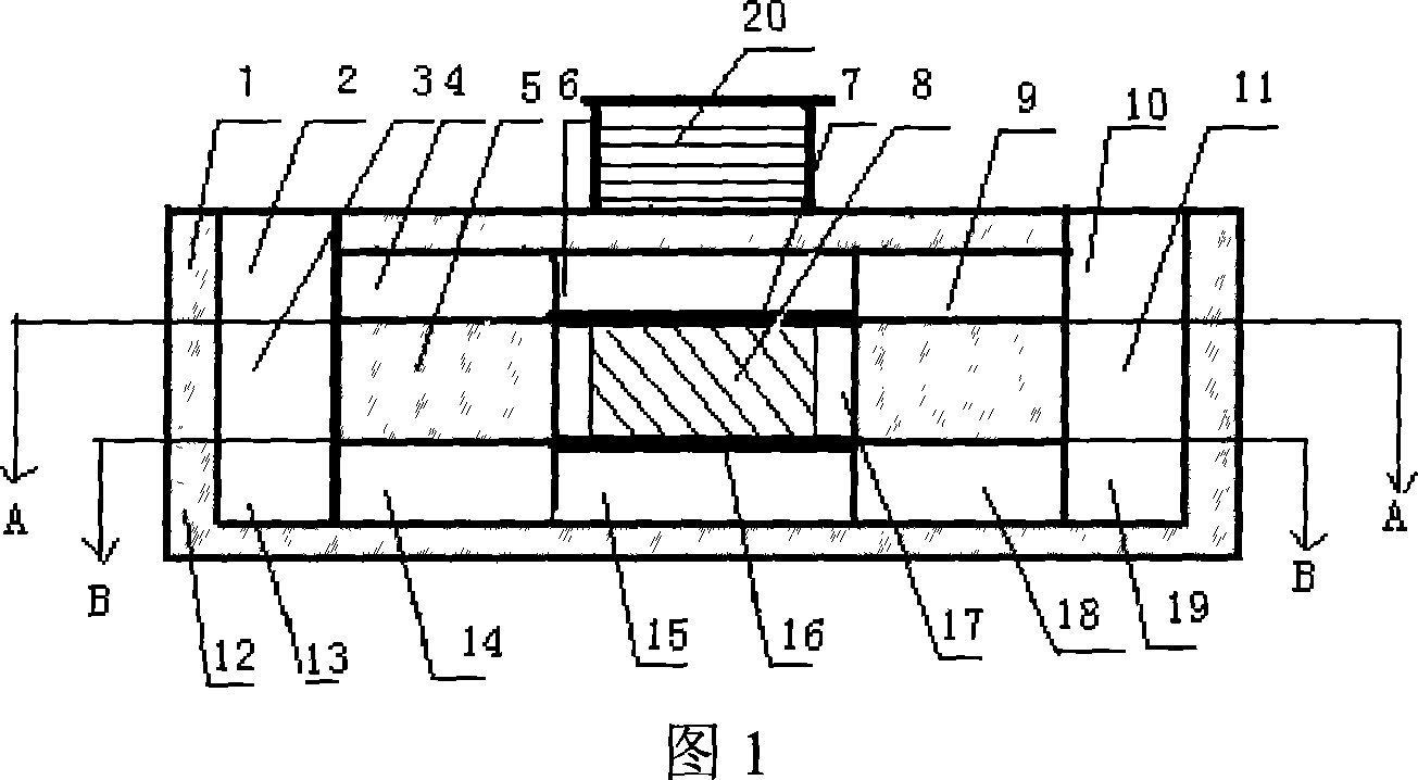
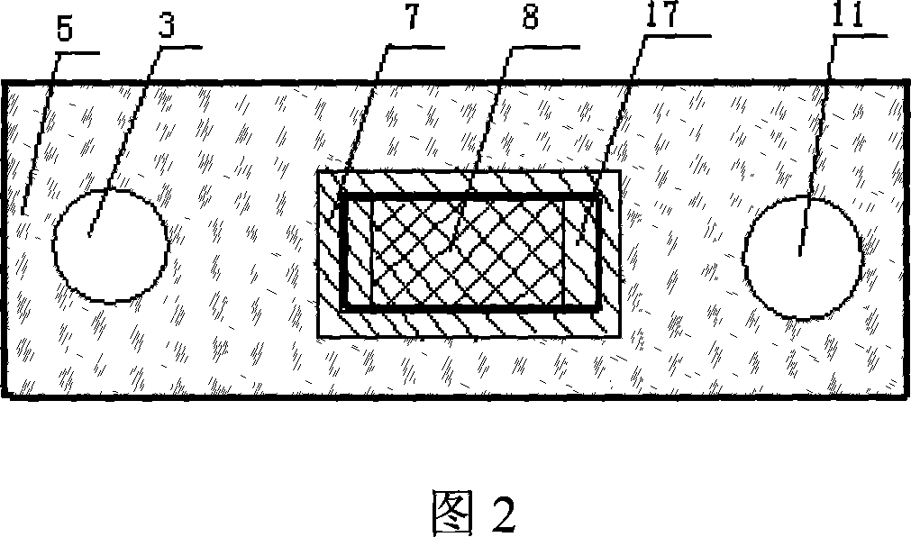
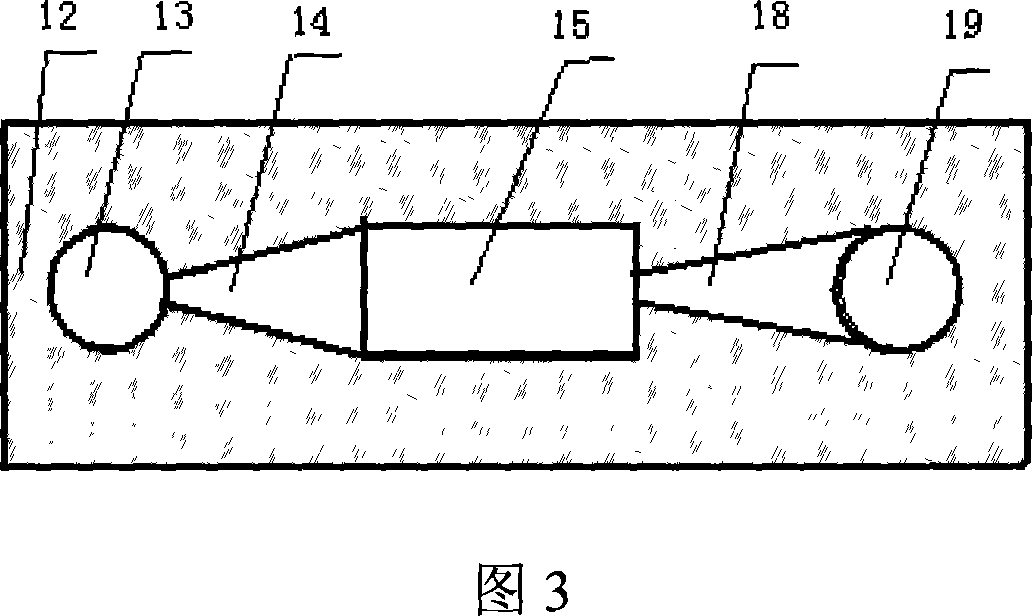
[0021] The present invention is described in more detail below in conjunction with accompanying drawing example:

[0022] As shown in Figure 1, Figure 2, and Figure 3, the pump body is divided into three parts: upper, middle and lower. The upper pump body 1 is provided with an upper pump chamber 6, which is connected to the water inlet and outlet holes 2, 10 through two left and right cone valves 4,9. There is a driving chamber 17 in the middle of the middle pump body 5, and there are water inlet and outlet holes 3, 11 on both sides, and they are all vertically corresponding to the upper pump chamber. The driving magnet 8 is placed in it, and the two films 7, 16 are respectively fixed on the driving chamber. Cavity 17 up and down. The lower pump body has a lower pump chamber 15 corresponding to the upper pump body. The lower pump chamber is also connected to the water inlet and outlet holes 13 and 19 through two cone valves 14,18, and the taper angle of each cone valve is equ...


PUM


Abstract

A micro pump free from pulse output and driven by electromagnet comprises the drive coil and drive magnet formed drive, up, middle and lower part formed micro pump, with the up pump having up pump cavity, left conical valve, right conical valve, water inlet hole, water outlet hole, up pump cavity connecting with water inlet and outlet holes through left and right conical valve, drive cavity between the middle pump, drive magnet set inside the drive cavity, fixed with thin film up and down inside the drive cavity, water inlet holes at both sides of the drive cavity, lower pump having pump cavity, left conical valve, right conical valve, water inlet hole, water outlet hole, lower pump cavity connecting with water inlet and outlet holes of two conical valves. It can work at relatively low voltage, with quick influence speed and safety.It can be applicable in medical field.

Description

(1) Technical field [0001] The invention relates to the field of microfluidic control and micromechanical technology, in particular to a delivery device for microfluidic liquid. (two), background technology [0002] The micro-flow system can accurately detect and control the flow rate of microliters per minute, and has an important role in the fields of micro-delivery, release, micro-liquid sampling, oil micro-injection, cell separation, cooling of integrated electronic components, micro-chemical analysis, and aerospace. Application prospects. As the core part of the system, the micropump has become a research hotspot of domestic and foreign scholars in recent years. Micropumps are widely used in biomedicine because they can infuse quantitative liquids and control the infusion speed, and are used to infuse special drugs that require accurate dosage and stable infusion speed, such as cardiotonic agents and vasoactive drugs. For example, diabetics used to inject a larger dos...

Claims


Application Information

Patent Timeline
Patent Type & Authority Applications(China)
IPC IPC(8): F04B43/04
Inventor 郭书祥叶秀芬裴志王天
Owner HARBIN ENG UNIV
Why Eureka
Try Eureka