Electromagnetic valve

A solenoid valve and valve body technology, applied in the field of solenoid valves, can solve problems such as increasing the leakage rate of equipment systems

Inactive Publication Date: 2007-09-26
INST OF SEMICONDUCTORS - CHINESE ACAD OF SCI
View PDF0 Cites 5 Cited by
  • Summary
  • Abstract
  • Description
  • Claims
  • Application Information

AI Technical Summary

Problems solved by technology

For a multi-channel gas source system, it is necessary to connect individual valves with pipes, requiring many welding joints and connection points, which increases the possibility of leakage rate of the equipment system

Method used


Image

  • Electromagnetic valve
  • Electromagnetic valve
  • Electromagnetic valve

Examples


Embodiment

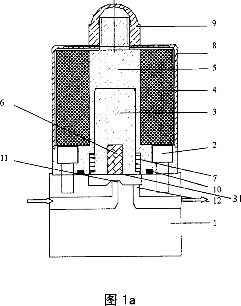
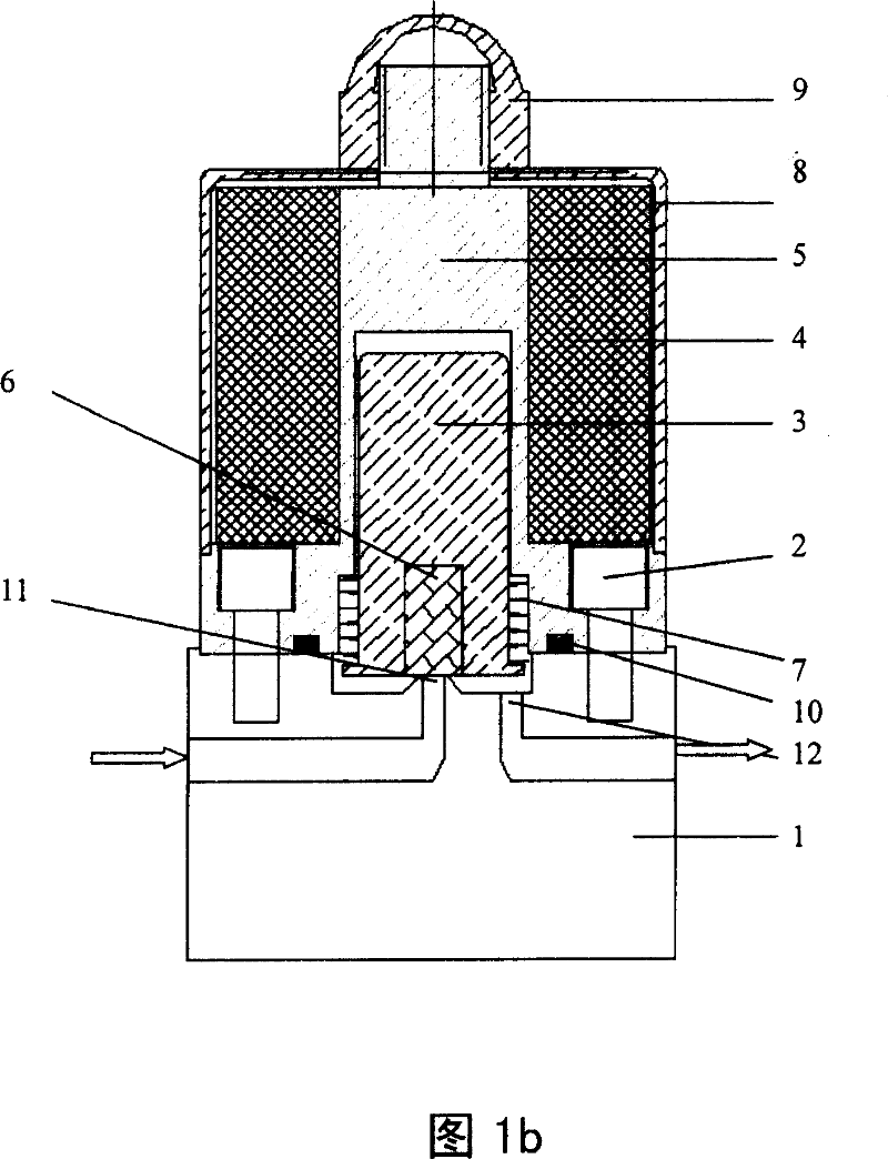
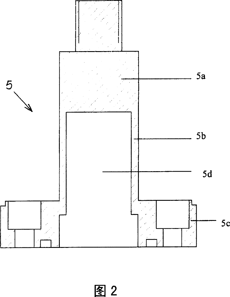
[0048] The solenoid valve of the present invention mainly includes a magnetic valve casing 8, a non-magnetic stainless steel valve seat 1, a stainless steel valve body 5, a magnetic stainless steel valve core 3, an electromagnetic coil 4, a spring 7 and a fluorine rubber strip 6, etc., and its structure is shown in Figure 1a and Figure 1. 1b, wherein Figure 1a is the valve open state, and Figure 1b is the valve closed state. The stainless steel valve body 5 is connected with the non-magnetic stainless steel valve seat 1 with stainless steel screws 2 and sealed with a sealing ring 10 . The upper half 5a and the lower half 5c of the stainless steel valve body 5 are made of magnetic stainless steel, the middle part 5b is made of non-magnetic stainless steel, the uppermost part of the stainless steel valve body 5 is threaded, and a stainless steel nut is used between the shell 8 9. Tighten it so that the magnetic path can be better formed when the electricity is turned on. There i...


PUM


Abstract

The electromagnetic valve comprises the non electromagnetic valve base locating at the utmost bottom of the electromagnetic valve, an air chamber formed at the upper center, guide valve opening and main valve opening from the air chamber to the outside wall, cross section of a valve being T shape and hallow, and the said valve connected with the non electromagnetic valve base through screw, with screw thread at the top, a magnetic valve core being a column, a round hole at the center of its end located at the center hollow part of the valve, a spring at the bottom of the said magnetic valve core and the valve, with the spring cased around the outside wall of the electromagnetic valve core, a Freon glue bar with the same size and shape of the magnetic valve core, putting into the hole of the magnetic valve core, an electromagnetic coil twisted around the outside wall of the valve, an outside shell cased outside of the valve with a round opening at the top, and the size being the same with the top of the magnetic valve and with nut fixed them in between.

Description

technical field [0001] The invention relates to the field of semiconductor equipment manufacturing, in particular to a solenoid valve in the gas path of semiconductor manufacturing equipment such as metal organic chemical vapor deposition equipment and hydride vapor phase epitaxy equipment. Background technique [0002] For metal-organic chemical vapor deposition equipment, hydride vapor phase epitaxy equipment, or other semiconductor manufacturing equipment, valves are the key to achieving fluid flow. Traditional pneumatic valves use compressed gas as the power source, and require auxiliary devices such as piping, compressed gas, and electromagnetic pilot valves to work, and the installation cost is high. In addition, pneumatic valves need diaphragms, bellows, etc. to transmit power, and diaphragms or bellows are made of a very thin (about 0.1 mm) metal and are easily broken; electromagnetic valves are directly driven by electricity, which has the advantages of easy assembl...

Claims


Application Information

Patent Timeline
IPC IPC(8): F16K1/00F16K31/06F16K11/22
Inventor 刘祥林焦春美赵风瑷
Owner INST OF SEMICONDUCTORS - CHINESE ACAD OF SCI
Why Eureka
Try Eureka