Optical multiplexed layer power optimized system and its method

A power optimization and optical multiplexing technology, which is applied in optical multiplexing systems, wavelength division multiplexing systems, multiplexing communications, etc., can solve the problem of narrowing the adjustable range, unavoidable bit errors, and difficulty in obtaining gain and loss and other issues to achieve the effect of ensuring that the system runs without errors

Active Publication Date: 2007-09-26
ZTE CORP
View PDF0 Cites 26 Cited by
  • Summary
  • Abstract
  • Description
  • Claims
  • Application Information

AI Technical Summary

Problems solved by technology

[0006] The existing optimization method is based on the network element level. The advantage of this network element level optimization method is that it is easy to adjust. The disadvantage is that it is not easy to obtain the overall situation of the gain and loss of each node in the OMS in the optical multiplexing section, so it cannot be realized auto

Method used


Image

  • Optical multiplexed layer power optimized system and its method
  • Optical multiplexed layer power optimized system and its method
  • Optical multiplexed layer power optimized system and its method

Examples


no. 1 example

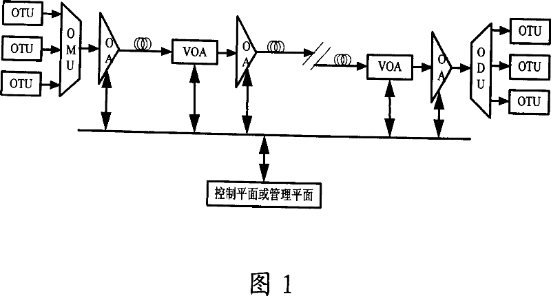
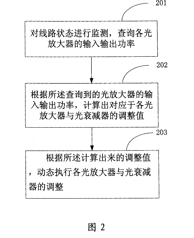
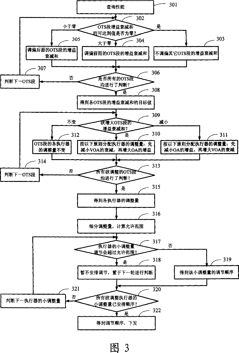
[0056] First, the control module calculates the gain and loss of each OTS section of the optical multiplexing section OMS according to the current state of the monitoring module, and uses the loss as a negative gain to calculate the sum of the gain and loss, which is the sum of gain attenuation.

[0057] Next, the target value of the gain attenuation sum of the OTS section is judged: the sum of the gain attenuation sums of each OTS section is the gain attenuation sum of the OMS section. Based on the principle that the gain attenuation sum tends to zero, according to the adjustable range of the optical amplifier and optical attenuator, the closest value of the gain attenuation sum of each OTS section to zero can be obtained, that is, the attainable value of the gain attenuation sum. When the achievable value of the gain attenuation sum of the OTS section is greater than zero, adjust the deviation according to the gain attenuation sum of the previous OTS section of the service fl...

no. 2 example

[0063] First, according to the monitored output power of the optical amplifier, calculate the difference between the current output power of each amplifier and the preset output power target value, where the target value can correspond to the first monitoring module of the optical multiplexing section Output optical power.

[0064] Then, according to the calculated difference, the adjustment value of each optical amplifier and optical attenuator is determined based on the principle that the output optical power of each optical amplifier tends to the target value.

no. 3 example

[0066] First, according to the monitored input and output power of the optical amplifier, the difference between the current line loss value corresponding to each optical transmission section and the preset loss target value is calculated, wherein the target value can be set manually.

[0067] Then, according to the calculated difference, the adjustment value of each optical amplifier and optical attenuator is determined based on the principle that the line loss of each optical transmission section tends to the target value.

[0068] In the step 203, according to the adjustment value issued by the control module, when the gain attenuation sum of the optical transmission section is to be increased, the attenuation of the optical attenuator is first reduced, and then the gain of the optical amplifier is increased; When the gain attenuation sum of the optical transmission section, first reduce the gain of the optical amplifier, and then increase the attenuation of the optical atte...


PUM


Abstract

The invention discloses a light multiplexing layer power optimizing system and method that includes monitoring module which is corresponding with said light amplifier and used to monitor input and output power of light amplifier; control module which is corresponding with said managing flat or control flat surface and used to control and query said monitoring module; executing module which is corresponding with said light amplifier and light attenuator; the three modules are connected via network managing system. The invention firstly monitors the line condition, inquires the input and output power of light amplifier, then calculates adjusting value which is corresponding with the light amplifier and light attenuator according to the input and output power of light amplifier inquired, the adjustment of light amplifier and light attenuator are executed dynamically based on adjusting value calculated. Using the method of the invention can optimize the power of light multiplexing layer gently, and guarantee the running of inerrability during the cause of optimization.

Description

technical field [0001] The invention relates to a wavelength division multiplexing transmission system in the communication field, in particular to an optical multiplexing layer power optimization system and a method thereof. Background technique [0002] The basic wavelength division multiplexing (WDM, Wavelength Division Multiplex) transmission system consists of optical transponder (OTU, Optical Transponder Unit), optical multiplexer (OMU, Optical Multiplexer Unit), optical amplifier (OA, Optical Amplifier), line fiber, optical Optical Demultiplexer Unit (ODU, Optical Demultiplexer Unit). The output from the OMU to the input of the ODU is an Optical Multiplex Section (OMS, Optical Multiplex Section). The output of the former OA to the input of the latter OA is an optical transmission section (OTS, Optical Transmission Section). [0003] The purpose of OMS power optimization in the optical multiplexing section of the wavelength division multiplexing transmission system i...

Claims


Application Information

Patent Timeline
IPC IPC(8): H04J14/02
CPCH04J14/0221
Inventor 张红宇王加莹夏焱
Owner ZTE CORP
Why Eureka
Try Eureka