

Elevator apparatus
A technology for elevators and braking devices, which is used in elevators, transportation and packaging, elevators and other directions in buildings, and can solve problems such as passenger discomfort and car inclination.
- Summary
- Abstract
- Description
- Claims
- Application Information
AI Technical Summary
Problems solved by technology
Method used
Image

Examples
Embodiment approach 1
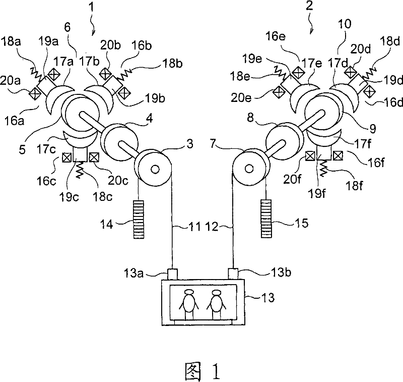
[0017] Fig. 1 is a block diagram showing an elevator apparatus according to Embodiment 1 of the present invention. In the figure, first and second driving devices (hoists) 1 and 2 are provided on the upper part of the hoistway. The first drive device 1 has a first drive pulley 3, a first motor 4 that rotates the first drive pulley 3, a first brake drum 5 as a brake rotating body that rotates integrally with the first drive pulley 3, and a first brake drum 5 for the first drive pulley 3. The first brake device 6 for braking the rotation of the brake drum 5 .
[0018] The 2nd driving device 2 has the 2nd drive pulley 7, the 2nd electric motor 8 that makes the 2nd drive pulley 7 rotate, the 2nd brake drum 9 as the brake rotary body that rotates integrally with the 2nd drive pulley 7 and the 2nd brake drum 9 for the 2nd drive pulley 7. The rotation of the brake drum 9 brakes the second brake device 10 .
[0019] A plurality of (only one is shown in the figure) first main ropes 1...
Embodiment approach 2
[0040]Next, FIG. 4 is a circuit diagram showing drive circuits for the first to sixth electromagnetic coils 20a to 20f of an elevator apparatus according to Embodiment 2 of the present invention. The overall structure of the elevator apparatus is the same as that of Embodiment 1 (FIG. 1). In the drawing, two first resistors 23a1 and 23a2 are provided in a circuit connected in parallel to the first electromagnetic coil 20a. The first resistors 23a1 and 23a2 are connected in parallel with each other and connected in series with the first diode 24a.
[0041] Between the first diode 24a and the first resistors 23a1 and 23a2, a first selection switch 25a for selectively connecting one of the first resistors 23a1 and 23a2 to the first diode 24a is connected. Also to the second to sixth electromagnetic coils 20b to 20f, similarly to the first electromagnetic coil 20a, second to sixth resistors 23b1 to 23f2 and second to sixth selection switches 25b to 25f are connected.
[0042] The...
Embodiment approach 3
[0052] Next, Fig. 6 is a block diagram showing a control unit that controls the first to sixth selection switches 25a to 25f of the elevator apparatus according to Embodiment 3 of the present invention. In this example, instead of the weighing devices 26 and 27, the command generator 31 generates a command for switching the selection switches 25a to 25f based on a signal from the car inclination sensor 30 that outputs a signal corresponding to the inclination of the car 13. . The command generator 31 shifts the timing of generating the braking force of the brake main bodies 16a to 16f in the same group, and outputs command signals to the selector switches 25a to 25f to cancel the inclination of the car 13 .
[0053] For example, when the car 13 is inclined so that the second rope connecting portion 13b is lower than the first rope connecting portion 13a, the fourth brake main body 16d generates a braking force slightly earlier than the first brake main body 16a, and the fifth ...
PUM
 Abstract
Description
Claims
Application Information