Return way structure of ball screw

A ball screw and ball technology, used in belts/chains/gears, mechanical equipment, transmission devices, etc., can solve the problems of interfering with the rolling of balls, the spacer touching the inner edge wall of the return curve, and the balls, etc., to achieve the degree of bending soothing effect

Active Publication Date: 2007-10-03
HIWIN TECH
View PDF4 Cites 9 Cited by
  • Summary
  • Abstract
  • Description
  • Claims
  • Application Information

AI Technical Summary

Problems solved by technology

[0013] However, in the ball screw, the return bend is usually designed in the end plug. Please refer to Figure 4. In the end plug 6, a section of linear guides 62 and 63 must be designed at the two ends of the return bend 61, respectively. For respectively connecting with the spiral groove 64 of the nut and the return hole 65 parallel to the axial direction of the nut, so the angle between the two ends of the return bend 61 will be less than 90 degrees, so if the U.S. Patent No. 6663285 is adopted The technical means of reducing the radius of the concentric center is applied to the end plug of the ball screw, which will cause a step difference G between the guides 62 and 63 at both ends of the return bend 61, the spiral groove 64 and the return hole 65, as shown in Figure 5 This will interfere with the circular rolling of the ball, and even the problem of ball jamming may occur
Therefore, the technical means of "concentric radius reduction" adopted in US Patent No. 6,663,285 cannot be transferred to the ball screw to solve the problem that the spacer touches the inner wall of the return flow curve

Method used


Image

  • Return way structure of ball screw
  • Return way structure of ball screw
  • Return way structure of ball screw

Examples


Embodiment Construction

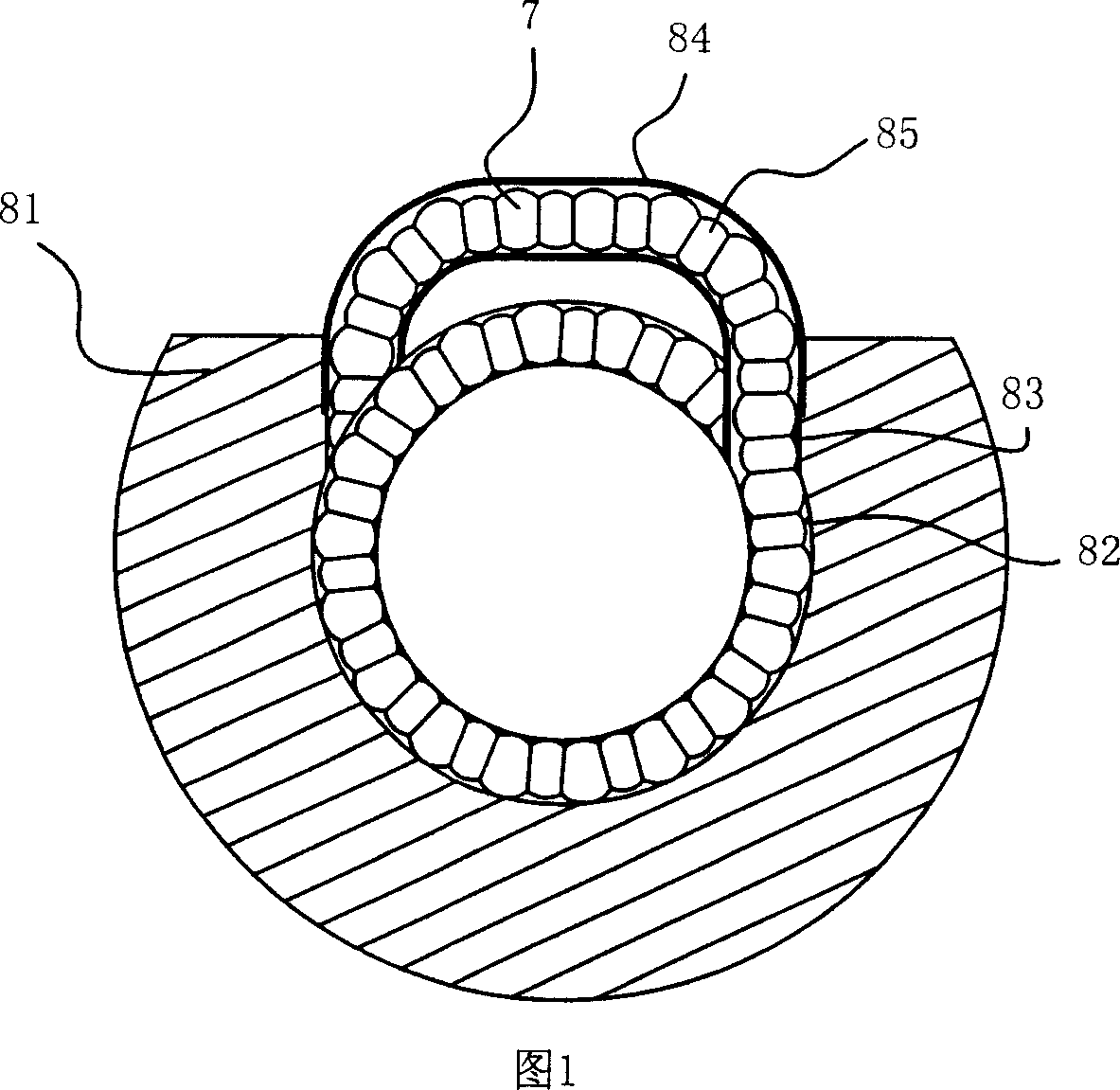
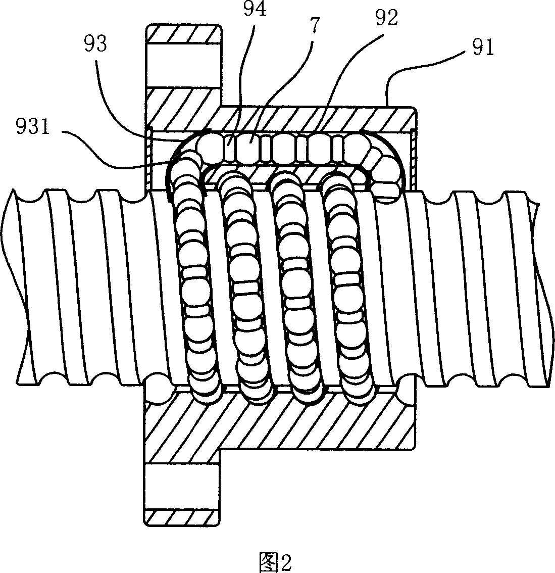
[0034] Please refer to Fig. 6-Fig. 8, the ball screw of the present embodiment is constituted by a screw 1 and a nut 2 passing through each other, and the screw 1 and the nut 2 are oppositely provided with spiral grooves 11, 21 for A plurality of balls 3 and a plurality of spacers 4 spaced between two adjacent balls are accommodated therein, and the nut 2 is provided with an axially extending return hole 22, and one end is respectively provided at the two ends of the return hole 22 Plug 5, and each end plug 5 has a return channel structure to respectively connect the spiral groove 21 and the return hole 22, so that the plurality of balls 3 and the plurality of spacers 4 can flow back and circulate in the nut 2.

[0035] Please refer to FIG. 7 , the backflow path structure includes a backflow bend 51 and two linear guides 52 and 53 respectively connecting the two ends of the backflow bend with the spiral groove 21 and the return hole 22 , the backflow bend 51 It is composed of ...


PUM


Abstract

The return way structure of ball screw is used for connecting the screw groove of screw nut and return flow hole so as to constitute one path for balls and distance pieces to circulate. Each of the distance pieces in shifting is held by two balls, so that the distance piece in the curved return flow path will be extruded inwards. The present invention shifts the circle center of the inner ace line in the curved return flow path outwards and increases its curvature radius to reduce curving degree, so that the distance piece extruded inwards will not collide with the inner guide surface in the curved return flow path for fluently passing through.

Description

technical field [0001] The invention relates to a ball screw, in particular to a return channel structure in which the return channel of the ball screw has a small inner curvature and a non-circular cross-section to facilitate the passage of spacers. Background technique [0002] In the ball screw, in order to make the internal balls roll smoothly and with low noise, spacers are usually installed between the balls to avoid collision and wear of the balls. [0003] When spacers are installed between the balls, the dimension design of the spacers is very important. If the size of the spacers is too small, the spacers between two adjacent balls are prone to loosening, and even the spacers may fall and get stuck. Problems with the balls; if the size of the spacer is too large, the outer edge of the spacer will easily contact the wall of the flow channel and cause interference problems, which will affect the normal operation of the balls. Therefore, the size of the spacer is gen...

Claims


Application Information

Patent Timeline
Patent Type & Authority Applications(China)
IPC IPC(8): F16H25/22
Inventor 陈彦羽邹健伟
Owner HIWIN TECH
Why Eureka
Try Eureka