Low complexity partial feedback zero beam forming method

A partial feedback, low-complexity technology, applied to baseband system components, preventing/detecting errors through diversity reception, etc., can solve high-complexity problems

Inactive Publication Date: 2007-10-03
UNIV OF SCI & TECH OF CHINA
View PDF0 Cites 10 Cited by
  • Summary
  • Abstract
  • Description
  • Claims
  • Application Information

AI Technical Summary

Problems solved by technology

However, this method still has high complexity

Method used


Image

  • Low complexity partial feedback zero beam forming method
  • Low complexity partial feedback zero beam forming method
  • Low complexity partial feedback zero beam forming method

Examples


Embodiment 1

[0080] In this embodiment, the base station is configured with 4 antennas, and each user is configured with 1 antenna. There are a total of 100 schedulable users in the cell, the normalized throughput requirement is 0.97, the scheduling correlation factor β=0.5, and the total signal-to-noise ratio P 0 / σ n 2 = 10, the channel of each user is a Rayleigh uncorrelated channel as an example to illustrate the implementation of a multi-user broadcasting system with partial user feedback zero-forcing beamforming.

[0081] In this configuration, the average channel gain according to (F3) is: g=E(∥h i ‖ 2 )=4.

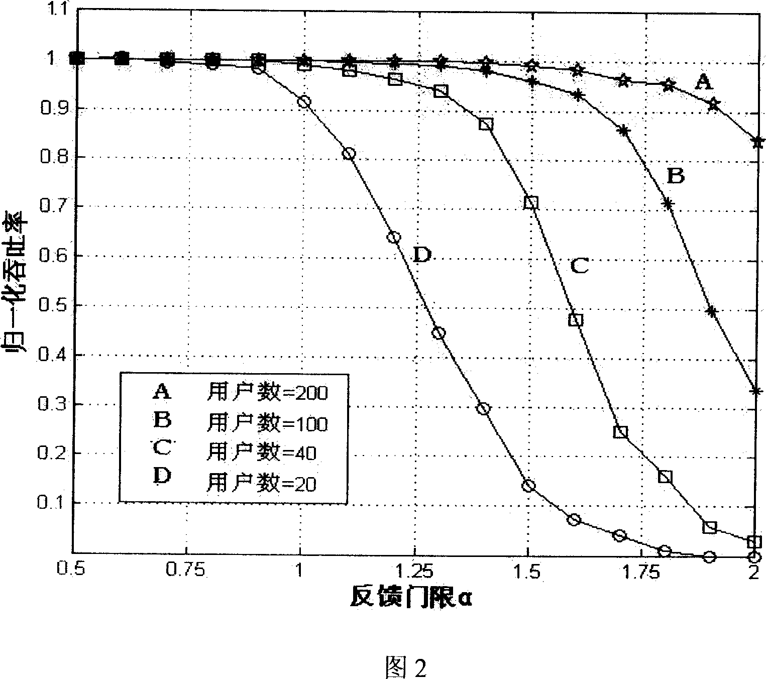
[0082] According to the relationship between the normalized throughput rate and the feedback threshold of 100 users, the base station sets the normalized feedback threshold α in the case of the normalized throughput rate of the feedback decision device to be 0.97 0 = 1.5.

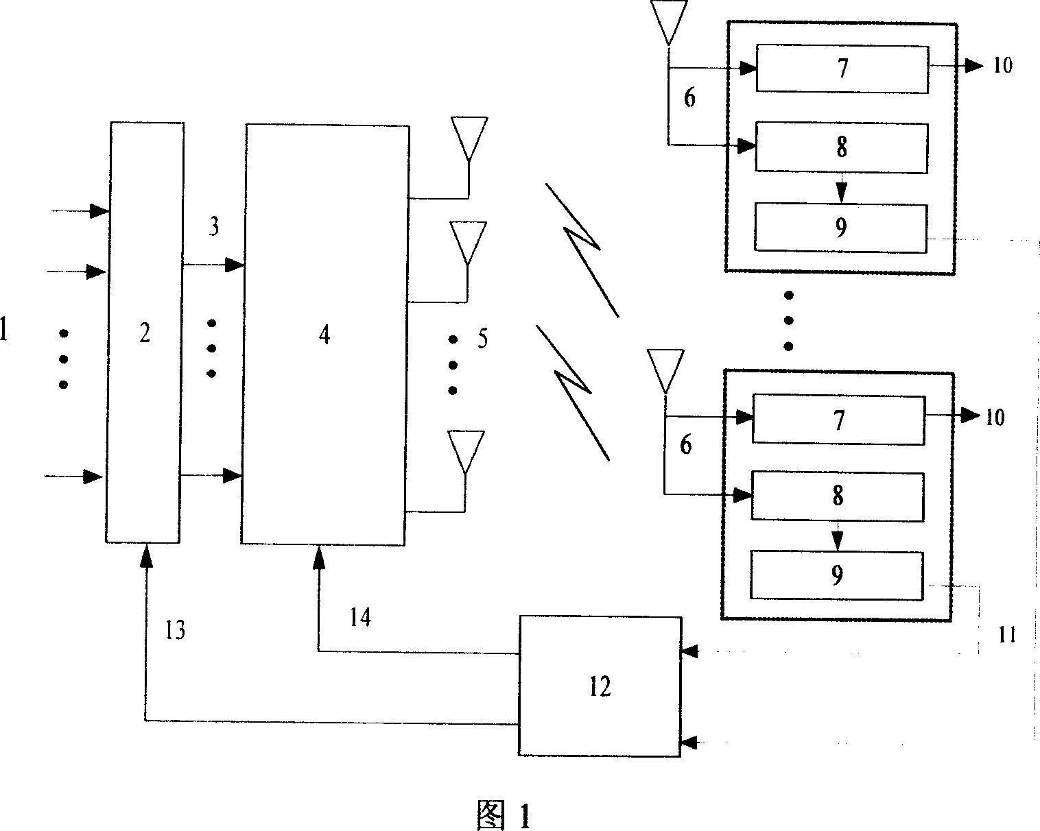
[0083] Figure 1 shows a block diagram of the implementation system structure of the low-complexity p...


PUM


Abstract

A low-complicacy forming method of partial feedback ZF wave beam includes passing channel state information of user through a decision unit with feedback threshold formed by throughput and user total number as well as emission antenna number first before said information is sent to feedback link, feedback channel state information of user with channel gain greater than feedback threshold back to base station through uplink feedback link and carrying out activation user-set dispatch only in all users participating in feedback by base station.

Description

Technical field: [0001] The invention belongs to the technical field of multi-antenna broadcast channel capacity in a mobile communication system, and in particular relates to a beamforming method for scheduling and preprocessing by a base station in a multi-antenna broadcast channel according to user feedback information. Background technique: [0002] Multi-user diversity is an effective method to improve the spectral efficiency of wireless systems, which has been extensively researched in the technical field of multi-antenna broadcast channel capacity in mobile communication systems. [0003] "International Institute of Electronics and Electrical Engineers Information Theory Journal" (IEEE Transactions on Information Theory, vol.49 No.7, July 2003, pp.1691--1706) introduced a multi-antenna at the base station and a single antenna at the user end Dirty paper coding technology is used in the broadcast channel to achieve downlink broadcast channel and capacity. However, due ...

Claims


Application Information

Patent Timeline
IPC IPC(8): H04L1/06H04L25/02
Inventor 邱玲刘宇鹏黄森华
Owner UNIV OF SCI & TECH OF CHINA
Why Eureka
Try Eureka