
Eureka
For R&D, Eureka makes reading and utilizing patents & technical documents easy.
Eureka AIR
Designed for self-driven R&D workflows. Generate viable solutions, solve complex R&D challenges, empower your innovation with AI.

Eureka Materials
Designed for material experts only. Revolutionize your material R&D, from search, analyze, to developing new materials.

TechResearch
Generate reliable direction feasibility study reports for your R&D in just a few steps.

TechSeek
Discover and master advanced knowledge NOW. Basics, ideas, possibilities, all at once.

TechMind
As an expert in R&D Theories, TechMind can generates customized viable solutions instantly.

TechRisk
Analyze your overall solution with one click, know your potential R&D risks in advance.

TechMonitor
Get weekly tech updates, stay abreast of the latest tech innovations and key insights.
Fluid container composed of two plates
A fluid container and cover technology, applied in the field of miniaturized fluid containers, can solve problems such as poor process control, poor channel height control, and destructive chemical treatment
- Summary
- Abstract
- Description
- Claims
- Application Information
AI Technical Summary
Problems solved by technology
Method used
Image

Examples
Embodiment Construction
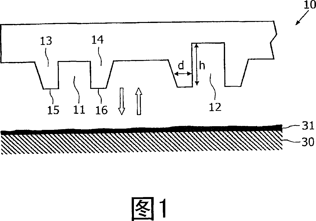
[0028] Microfluidic devices are of great interest in many fields, from electronic cooling to biosensors. Typically, the microchannels of the device are fabricated by forming trenches in a substrate (such as silicon, glass or plastic) and covering the structured substrate with a flat cover plate. For tiny channels, it is crucial to have high channel precision (because the flow resistance is proportional to the fourth power of the channel height), and the channel precision is determined not only by the structuring of the substrate, but also by the structure of the lid. combined process decision.
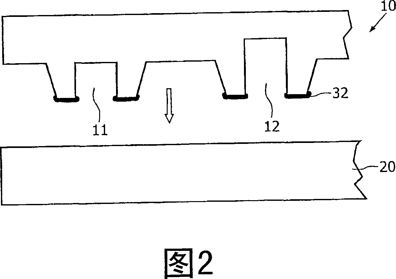
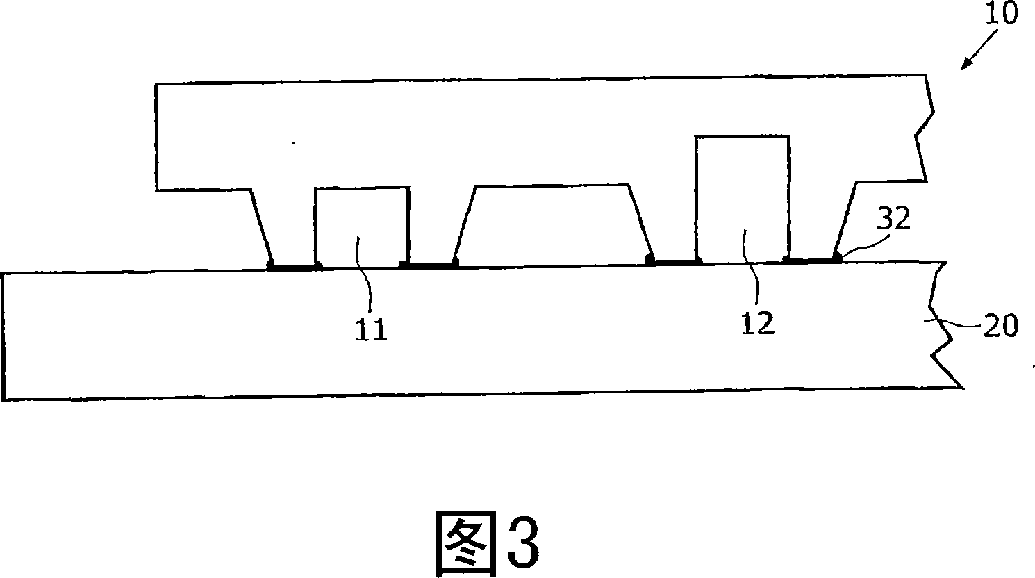
[0029] Basically, the bonding can be done using a variety of techniques, either direct bonding, where the lid and substrate are bonded directly, or indirect bonding, where an additional "glue" layer is used to achieve the bond. Direct techniques are limited in possible material combinations. In order to obtain a low-cost device, the substrate is usually made of plastic.
[0030] Dir...
PUM
 Abstract
Description
Claims
Application Information
 - R&D Engineer
- R&D Manager
- IP Professional
- Industry Leading Data Capabilities
- Powerful AI technology
- Patent DNA Extraction
Browse by: Latest US Patents, China's latest patents, Technical Efficacy Thesaurus, Application Domain, Technology Topic, Popular Technical Reports.
© 2024 PatSnap. All rights reserved.Legal|Privacy policy|Modern Slavery Act Transparency Statement|Sitemap|About US| Contact US: help@patsnap.com