Flat knitting machine guide bar controlling device

A control device and knitting machine technology, which is applied to knitting, warp knitting, and flat warp knitting machines, and can solve problems such as difficult transportation, expensive, and heavy knitting machines

Inactive Publication Date: 2007-10-10
KARL MAYER TEXTILMASCHFAB GMBH
View PDF3 Cites 8 Cited by
  • Summary
  • Abstract
  • Description
  • Claims
  • Application Information

AI Technical Summary

Problems solved by technology

[0033] Also, due to the large number of internal components, knitting machines become bulk

Method used


Image

  • Flat knitting machine guide bar controlling device
  • Flat knitting machine guide bar controlling device
  • Flat knitting machine guide bar controlling device

Examples


Embodiment Construction

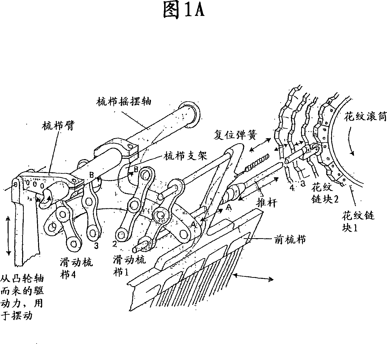
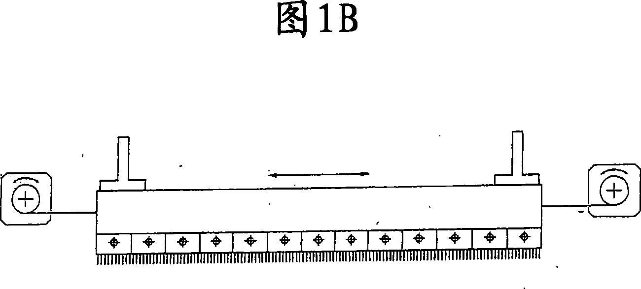
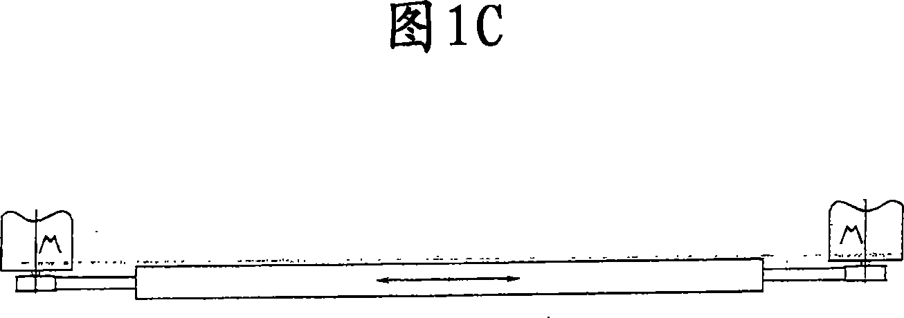
[0050] With reference to the above-mentioned accompanying drawings, the bar 2 control device 1 of the flat knitting machine in the present invention includes: a linear motor 10 for causing the bar 2 to move in translation, and a motor 10 for making the bar 2 swing substantially perpendicular to the direction of the translational movement The device 40, and the transmission device 20 that transmits the translational motion initiated by the linear motor 10 to the bar 2, so that the bar 2 can swing.

[0051] The device 1 in the present invention is characterized in that: the transmission device 20 includes a first transmission element 21 connected and integrated with the linear motor 10 , and a second transmission element 24 that can be integrally connected with the bar 2 . The first transmission element 21 also has a first guide member 22 in which the second transmission element 24 is movably connected.

[0052] The first guide 22 preferably has a substantially curved shape, so ...


PUM


Abstract

A control device ( 1 ) for thread-guide bars ( 2 ) of linear knitting machines, comprising a linear motor ( 10 ) designed to impart a translational motion to the thread-guide bar ( 2 ), means ( 40 ) for moving the thread-guide bar ( 2 ) according to an oscillating motion basically perpendicular to the translational motion, and transmission means ( 20 ) for transmitting to the thread-guide bar ( 2 ) the translational motion of the linear motor ( 10 ), thus enabling the oscillating motion. The device ( 1 ) is characterized in that the transmission means ( 20 ) include a first transmission element ( 21 ) associated to and integral with the linear motor ( 10 ), and a second transmission element ( 24 ) that can be integrally connectable to the thread-guide bar ( 2 ). Moreover, the first transmission element ( 21 ) has a first guide ( 22 ) having preferably a basically curved shape, in which the second transmission element ( 24 ) is movably engaged.

Description

technical field [0001] The invention relates to a control device for a bar of a flat knitting machine (such as a Raschel warp knitting machine or other similar knitting machines). Background technique [0002] Known flat knitting machines have a plurality of bars for carrying a plurality of thread clamping elements, usually called thread guides. The comb bar is set so that the yarn connected to the yarn guide can be correctly delivered to the knitting needles of the knitting machine, and knitted fabrics are woven with known techniques, that is, the newly delivered yarn enters the previous knitting needle. The formed loop is knitted while the loop is released and becomes part of the knitted fabric being manufactured. [0003] To accomplish the knitting task, the bar makes two basic movements simultaneously, a first linear movement in front of each needle hook, often called a "traversing movement", and an oscillating movement next to each needle, To alternately bring the yar...

Claims


Application Information

Patent Timeline
IPC IPC(8): D04B27/26D04B23/00
CPCD04B27/26
Inventor 蒂贝里奥·洛纳蒂
Owner KARL MAYER TEXTILMASCHFAB GMBH
Why Eureka
Try Eureka