Automatic detection equipment

An automatic detection and equipment technology, applied in the direction of lighting and heating equipment, measuring devices, optical testing flaws/defects, etc., can solve the problems of unstable product quality, product short circuit, waste of manpower, etc., to improve imaging clarity, exit light Stabilization, light loss reduction effect

Inactive Publication Date: 2010-05-12
SUZHOU MINGFU AUTOMATIC SCI & TECH
View PDF0 Cites 0 Cited by
  • Summary
  • Abstract
  • Description
  • Claims
  • Application Information

AI Technical Summary

Problems solved by technology

One method of visual inspection is to rely on the inspector to use the visual method to inspect, which is a waste of time and manpower. The other is to use automatic inspection equipment to capture images of solder joints, identify the images of solder joints and compare them with characteristic images. Compare to judge the quality of solder joints
[0004] Under the existing technology, the automatic detection equipment has the problem of inaccurate judgment of solder joints. For normal solder joints, it is often misjudged as over-welded or under-welded; for over-welded or under-welded solder joints, it is often judged as normal solder joints. Short circuit or open circuit of the product, failure to achieve normal functions, wrongly judged defective products put into subsequent production not only affect the yield rate of subsequent processes, but also products with less soldering often cause finished product defects to be unable to be detected in time, and the quality of finished products is unstable, affecting the company's reputation Goodwill, the biggest factor that causes inaccurate judgment of solder joints is that the background and solder joints are easily confused, and the images of solder joints cannot be accurately captured, so that the solder joints cannot be accurately identified and judged

Method used


Image

  • Automatic detection equipment
  • Automatic detection equipment
  • Automatic detection equipment

Examples


Embodiment Construction

[0016] The present invention will be described in detail below in conjunction with the accompanying drawings.

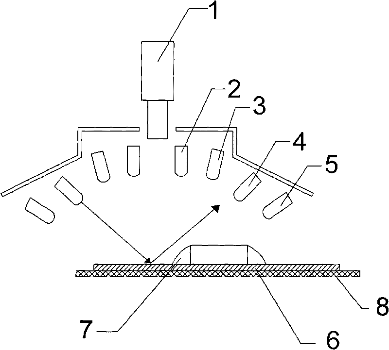
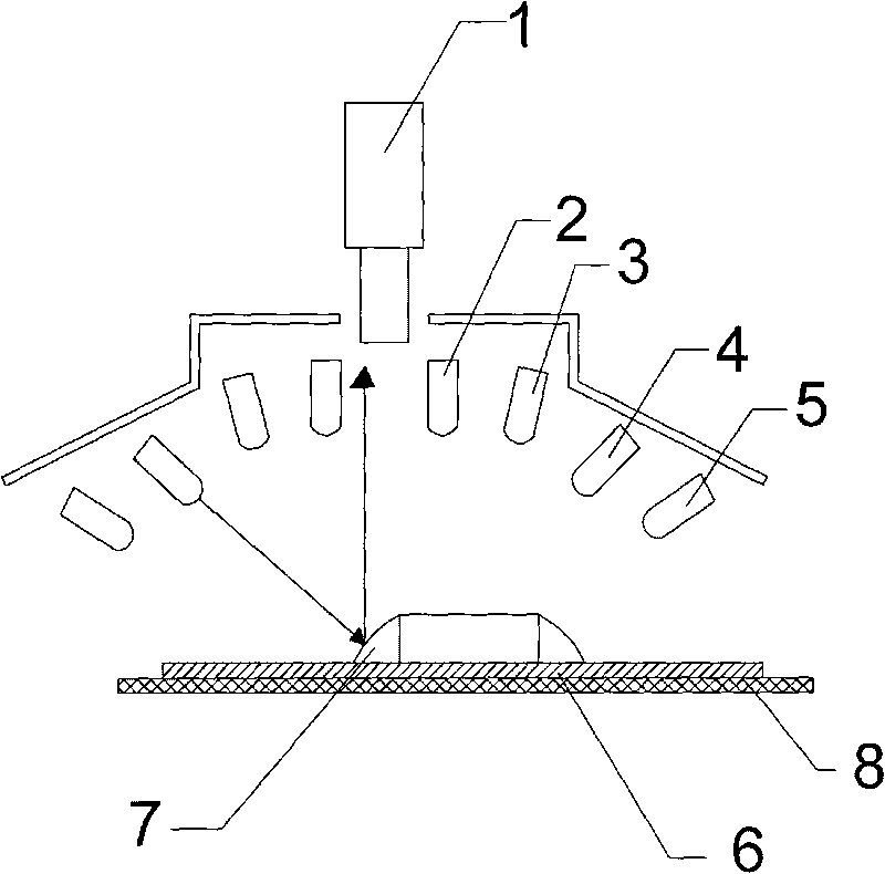
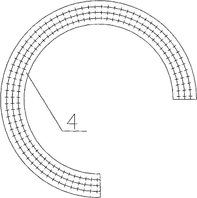
[0017] as attached figure 1 As shown, an automatic detection device is used for soldering detection, which includes a camera 1, a light source surrounding the camera 1, a carrying platform 8 located below the camera 1 and the light source, a computer for image comparison, and a carrying platform 8 It also includes an automatic transmission device for automatically conveying the detected items. The light source is 4 ring light sources. The 4 ring light sources are composed of light-emitting diodes of various colors. The white ring light source 2, red ring light source 3, green ring light source 4, and blue ring light source 5 are arranged in sequence below. After the axis centers of each ring light source coincide, you only need to adjust the angle of each ring light source to make each ring light source project to The same position and overlap are convenient for tar...


PUM


Abstract

The invention discloses automatic detection equipment, which comprises a camera (1), light sources, a bearing platform (8) and a computer, wherein the light sources surround the camera (1); the bearing platform (8) is positioned below the camera (1) and the light sources; the computer is used for contrasting images; the light sources are four annular light sources which are a white annular light source (2), a red annular light source (3), a green annular light source (4) and a blue annular light source (5) respectively arranged from top to bottom in sequence; an incident angle of each annular light source is greater than that of the adjacent annular light source positioned above and is smaller than that of the adjacent annular light source positioned below; and the green annular light source (4) consists of 198 LEDs. The automatic detection equipment has the advantage that: the automatic detection equipment has high judgment accuracy for soldered dots of tin soldering, and is not easy to misjudge.

Description

technical field [0001] The invention relates to an automatic detection device, in particular to an automatic detection device for detecting solder joints. Background technique [0002] The final process of soldering is inspection. Due to the defects of soldering joints, the solder joints need to be inspected after the production is completed. There are roughly two types of welding inspections: one is pre-welding inspection, that is, checking the surface of the base metal, solder , flux, etc. meet the appropriate welding conditions; the second is post-welding inspection, that is, checking whether the welding is reliable and whether there are welding defects. Post-welding inspection can not only find all defects through strict inspection to ensure the quality of shipped products, but also find large quantities of defective products in time to prevent subsequent defective products from continuing to occur. The most important thing is the analysis of defective products after wel...

Claims


Application Information

Patent Timeline
Patent Type & Authority Applications(China)
IPC IPC(8): G01N21/01G01N21/88F21V19/00F21Y101/02F21Y103/33F21Y115/10
Inventor 庄春明
Owner SUZHOU MINGFU AUTOMATIC SCI & TECH
Why Eureka
Try Eureka