

Film residual stress measuring structure and its producing and testing method
A technology of residual stress and thin film, which is applied in the field of measurement, can solve the problems of large layout space, structural arrays that cannot measure residual compressive stress and tensile stress at the same time, occupation, etc., and achieve the effect of improving utilization rate and saving layout space
- Summary
- Abstract
- Description
- Claims
- Application Information
AI Technical Summary
Problems solved by technology
Method used
Image


Examples
Embodiment 1
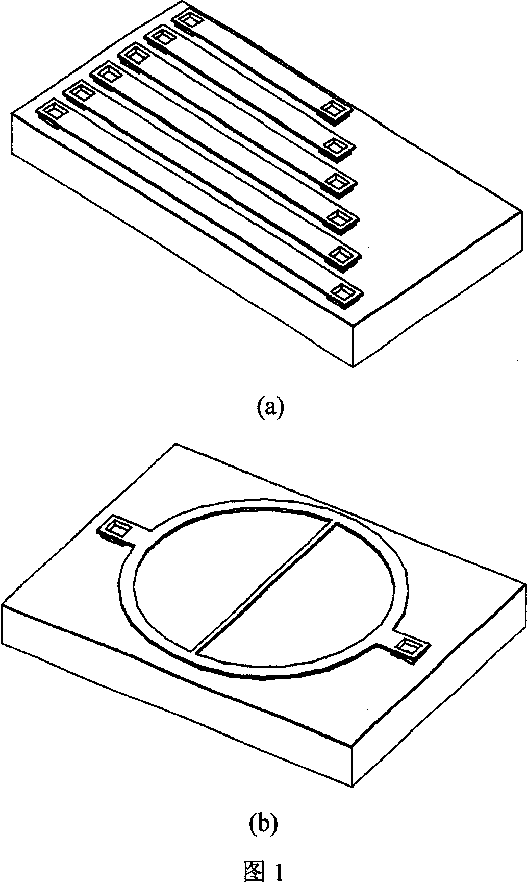
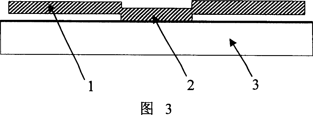
[0032] Referring to Fig. 2, Fig. 3, film residual stress measurement structure 6 comprises a test plate 1, a support anchor point 2 and sacrificial layer 4, test plate 1 is suspended on the substrate 3 by support anchor point 2, and sacrificial layer 4 is filled in the test Between plate 1 and base 3. The test plate 1 is circular and transparent under the light of the microscope 9 . The support anchor point 2 is also circular and located in the center of the test plate 1 . The thickness of the test plate 1 and the height of the supporting anchor point 2 are consistent with the device to be tested for stress. Due to technological reasons, the test plate 1 has a depression at the support anchor point 2, and the shape of the depression is a circle consistent with the shape of the anchor point.
[0033] The thin-film residual stress measurement structure 6 is manufactured using surface silicon micromachining technology, as shown in Figure 7, and its processing process includes t...
Embodiment 2
[0041] Referring to Fig. 4 and Fig. 5, the thin film residual stress measurement structure 6 includes a test plate 1, a support anchor point 2 and a sacrificial layer 4, the test plate 1 is suspended on the substrate 3 through the support anchor point 2, and the sacrificial layer 4 is filled in the test Between plate 1 and base 3. The test plate 1 is a square with a square hole in the middle, and is transparent under the light of the microscope 9 . The supporting anchor point 2 is a square ring located on the outer periphery of the test plate 1 . The thickness of the test plate 1 and the height of the supporting anchor point 2 are consistent with the device to be tested for stress. Due to technological reasons, the test plate 1 has a depression at the support anchor point 2, and the shape of the depression is a square ring consistent with the shape of the anchor point.
[0042] The thin-film residual stress measurement structure 6 is manufactured using surface silicon microm...
Embodiment 3
[0050] Referring to Fig. 6, the thin film residual stress measurement structure 6 is made up of a series of test flat plate 1 arrays whose radii are uniformly increased, and each test flat plate 1 is suspended on the substrate 3 by a supporting anchor point 2, and the sacrificial layer 4 is filled between the test flat plate 1 and the test flat plate 1. Between base 3. All test plates 1 are round and opaque under the light of the microscope 9 . All support anchor points 2 are also circular and located in the center of the corresponding test plate 1 . The thickness of each test plate 1 and the height of the supporting anchor point 2 are consistent with the device to be tested for stress. Due to technological reasons, the test plate 1 has a depression at the support anchor point 2, and the shape of the depression is a circle consistent with the shape of the anchor point.
[0051] The thin-film residual stress measurement structure 6 is manufactured using surface silicon microm...
PUM
 Abstract
Description
Claims
Application Information