Displacement superposed piezoelectric engaging motor and its exciting method

A superposition and displacement technology, applied in the direction of piezoelectric effect/electrostrictive or magnetostrictive motors, electrical components, generators/motors, etc., can solve the problem of large ineffective deformation of piezoelectric harmonic motors and complex motor structures , low transmission efficiency and other issues, to achieve the effect of easy adjustment of speed, saving work space and high rotation accuracy

Active Publication Date: 2007-10-10
View PDF0 Cites 16 Cited by
  • Summary
  • Abstract
  • Description
  • Claims
  • Application Information

AI Technical Summary

Problems solved by technology

[0004] The present invention aims to solve the problems of large ineffective deformation, large power loss, complex motor structure, large wear and low transmis

Method used


Image

  • Displacement superposed piezoelectric engaging motor and its exciting method
  • Displacement superposed piezoelectric engaging motor and its exciting method
  • Displacement superposed piezoelectric engaging motor and its exciting method

Examples


specific Embodiment approach 1

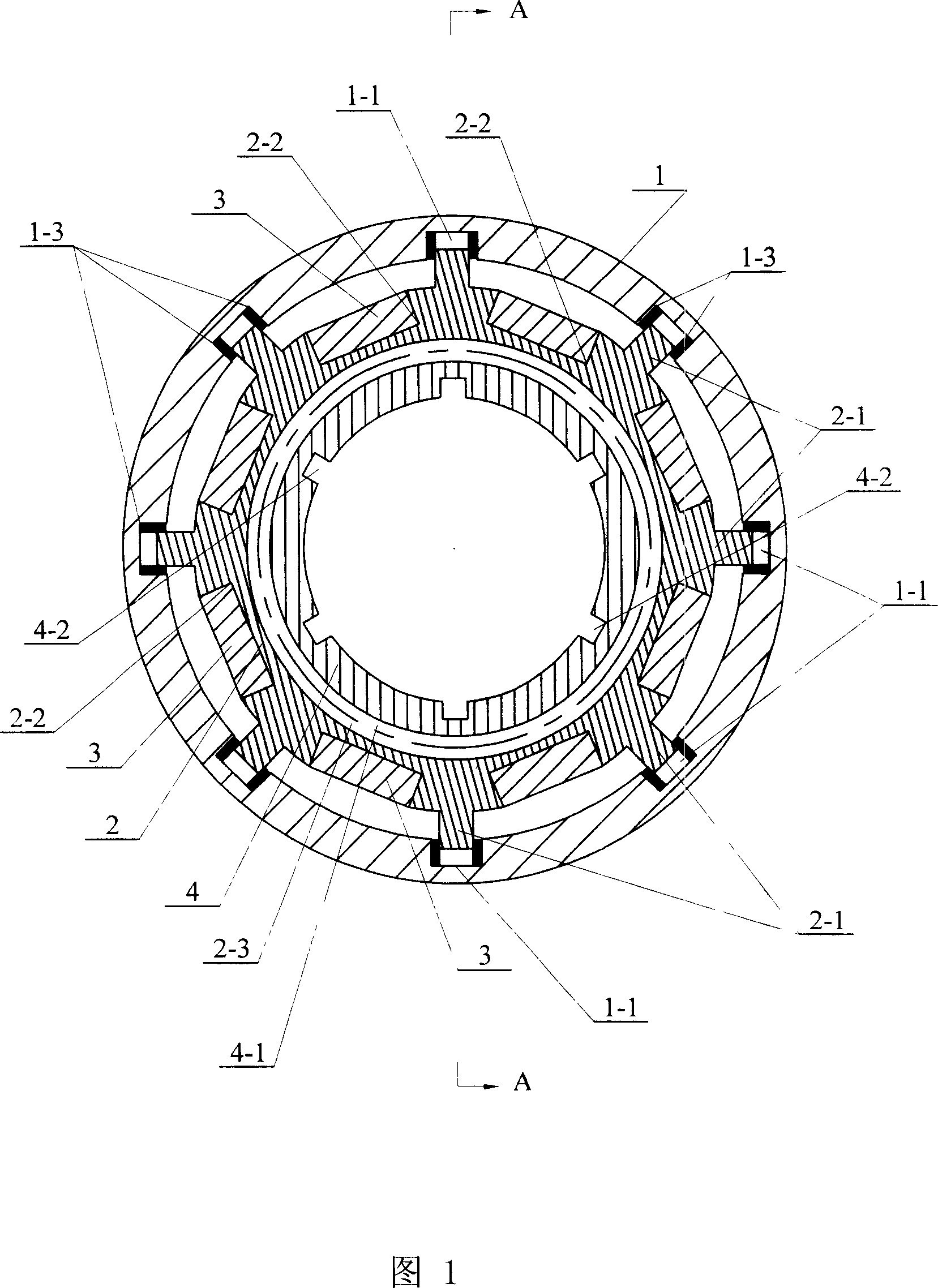
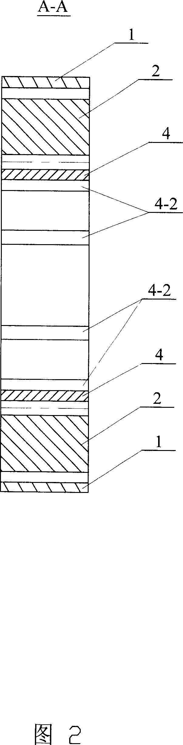
[0017] Specific Embodiment 1: This embodiment is described in conjunction with Fig. 1 and Fig. 2. Its motor is composed of a housing 1, an internally toothed elastic wheel 2, a plurality of piezoelectric ceramic bodies 3, and an externally toothed rigid wheel 4;

[0018] A plurality of rectangular through-slots 2-2 are evenly opened on the outer circumference of the inner-toothed elastic wheel 2, and each rectangular through-slot 2-2 is evenly provided with a plurality of rectangular through-slots 2-2 on the outer circumference of the inner-toothed elastic wheel 2. 2. A piezoelectric ceramic body 3 is inlaid in each rectangular slot 2-2. The direction of piezoelectric ceramic body 3 energization and elongation is parallel to the tangent line of the outer circular surface of the inner-toothed elastic wheel 2, and the inner-toothed elastic wheel A plurality of protruding prongs 2-1 on the outer surface of the housing 1 are connected to a plurality of corresponding grooves 1-1 on ...

specific Embodiment approach 2

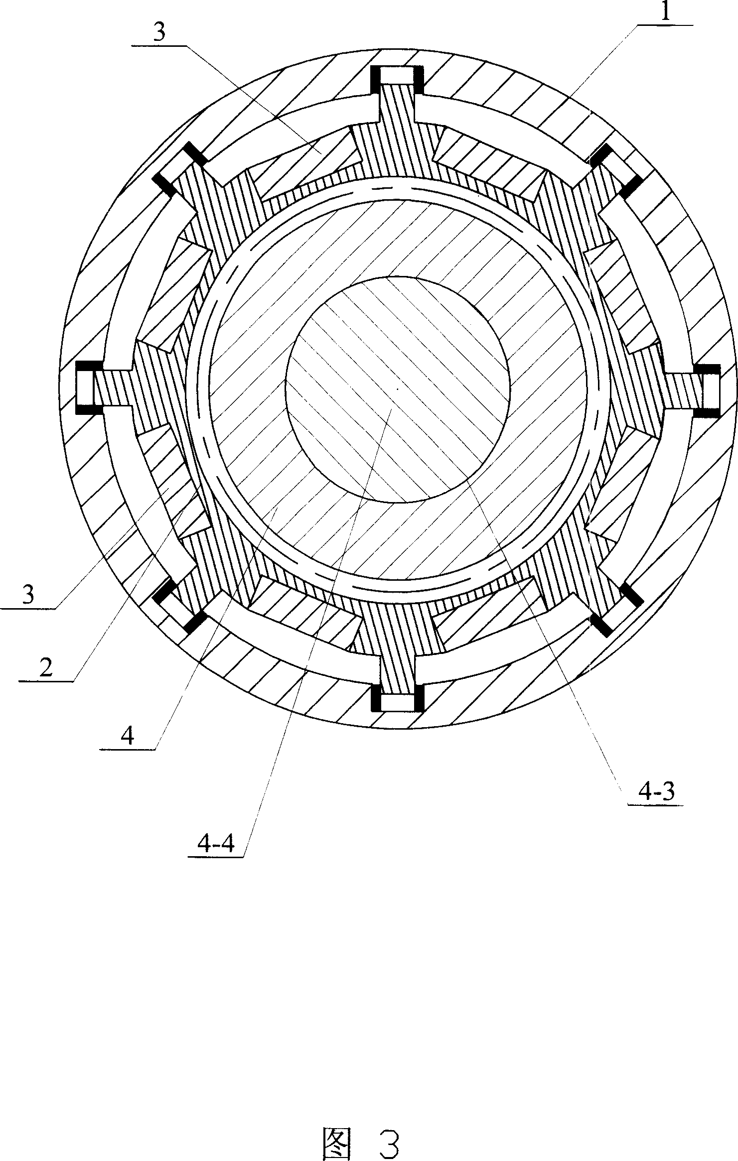
[0023] Embodiment 2: This embodiment is described with reference to FIG. 3 and FIG. 4 . The difference between this embodiment and Embodiment 1 is that an output shaft 4-4 is embedded in the inner circular hole 4-3 of the externally toothed rigid wheel 4 . Other compositions and connections are the same as in the first embodiment.

Embodiment approach

[0024] Another embodiment of the present invention (as shown in Figure 4):

[0025] This method is composed of an externally toothed elastic wheel 8-1, a plurality of piezoelectric ceramic bodies 8-2, and an internally toothed rigid wheel 8-3; a plurality of rectangular through slots 8 are opened on the inner surface of the externally toothed elastic wheel 8-1 -1-1, each rectangular slot 8-1-1 is inlaid with a piezoelectric ceramic body 8-2, the piezoelectric ceramic body 8-2 is electrified and elongated in the same direction as the outer gear elastic wheel 8-1 The tangent lines of the inner circle surface are parallel, the outer teeth 8-1-2 of the outer tooth elastic wheel 8-1 are meshed with the inner teeth 8-3-1 of the inner tooth rigid wheel 8-3, and the outer teeth of the outer tooth elastic wheel 8-1 The number of teeth of the teeth 8-1-2 is smaller than that of the inner teeth 8-3-1 of the inner tooth rigid wheel 8-3.


PUM

PropertyMeasurementUnit
Elastic modulusaaaaaaaaaa

Abstract

The invention is in order to solve issues that the current piezoelectric harmonic motor possesses disadvantages of large non-effective deformation, large power loss, complicated structure of motor, large abrasion, and low drive efficiency. Multiple rectangular through grooves are made on the excircle face of internal tooth elastic wheel. One piece of piezoelectric ceramic body is inserted to each through groove. Stretchy direction of electrified piezoelectric ceramic body is parallel to tangent of the excircle face. Through corresponding multiple grooves to inner circle, bulges on the excircle face are connected to each other. Internal teeth of internal tooth elastic wheel engage to external teeth of external tooth rigid wheel partially. Advantages of the invention are: output of large torque in low speed, high energy conversion efficiency, long service life, high precision of rotation, and no electromagnetic interference etc.

Description

technical field [0001] The present invention relates to the technical field of piezoelectric meshing motors Background technique [0002] The traditional ultrasonic motor uses the inverse piezoelectric effect of piezoelectric ceramics to make the surface particles of the stator generate elliptical ultrasonic vibrations, and the rotor obtains the driving force through contact and friction with the stator, so this kind of motor is also called piezoelectric friction motor. Due to the sliding friction between the stator and the rotor of this motor, its transmission efficiency is low, there are wear problems, and it is not suitable for continuous work. [0003] The piezoelectric harmonic motor developed in recent years is a meshing transmission motor based on the theory of harmonic transmission. It uses piezoelectric ceramics as the driver to replace the wave generator of the harmonic transmission device. By controlling the expansion and contraction deformation of each group of ...

Claims


Application Information

Patent Timeline
IPC IPC(8): H02N2/12F16H3/54
Inventor 曲建俊耿牛牛梁国伟李华夏杨佳文刘学程廷海
Why Eureka
Try Eureka