Method and system for regulating feeding wire speed

A technology for speed regulation system and wire feeding, which is applied in the direction of control system, DC motor speed/torque control, excitation or armature current control, etc. Accurate sampling of electromotive force and other issues to achieve the effect of stable rotation speed

Active Publication Date: 2007-10-10
PANASONIC WELDING SYST TANGSHAN
View PDF0 Cites 18 Cited by
  • Summary
  • Abstract
  • Description
  • Claims
  • Application Information

AI Technical Summary

Problems solved by technology

In fact, for the same motor, when the load force of the motor is constant, t d The time period is a constant, but when the motor load force changes, t d The time period is variable, therefore, the t d The time period is used as a constant constant as the delay time of sampling control, and it cannot accurately sample the induced electromotive force when the load force of the motor changes. In actual work, due to the influence of various factors, the load force of the wire feeding motor Therefore, in this method, accurate sampling of the electromotive force cannot be realized, and the speed of the wire-feeding motor is greatly affected by the disturbance of the wire-feeding resistance and the lengthening of the wire-feeding motor control line

Method used


Image

  • Method and system for regulating feeding wire speed
  • Method and system for regulating feeding wire speed
  • Method and system for regulating feeding wire speed

Examples


Embodiment Construction

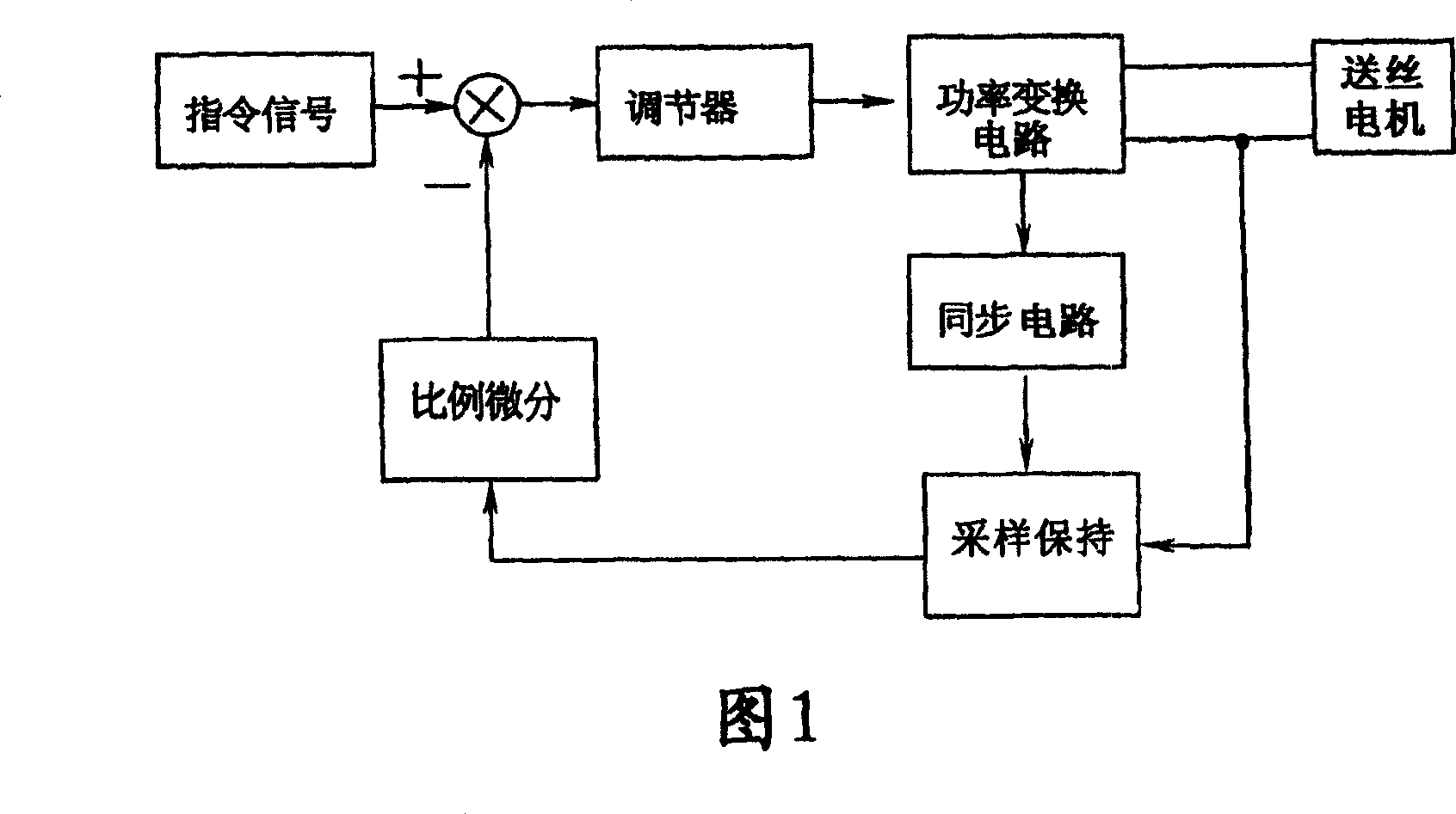
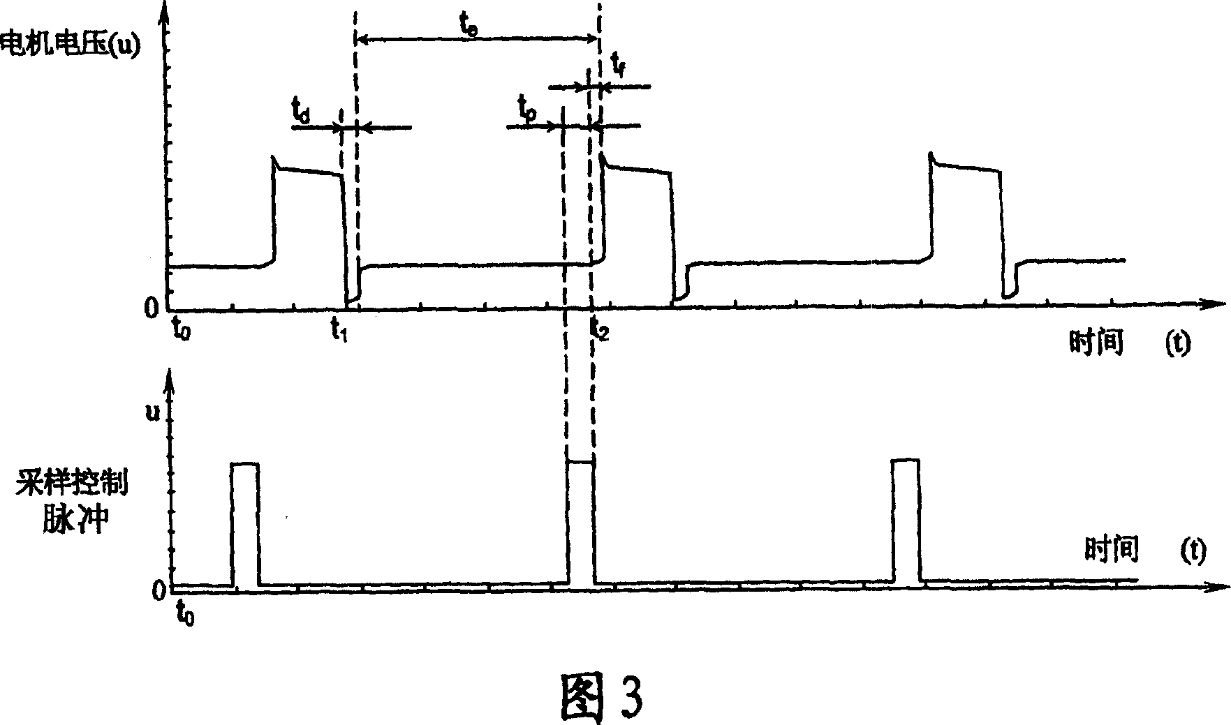
[0020] Firstly, the wire feeding sampling method of the present invention will be described with reference to the time sequence of the induction electromotive force feedback sampling control of the speed control of the wire feeding motor in FIG. 3 .

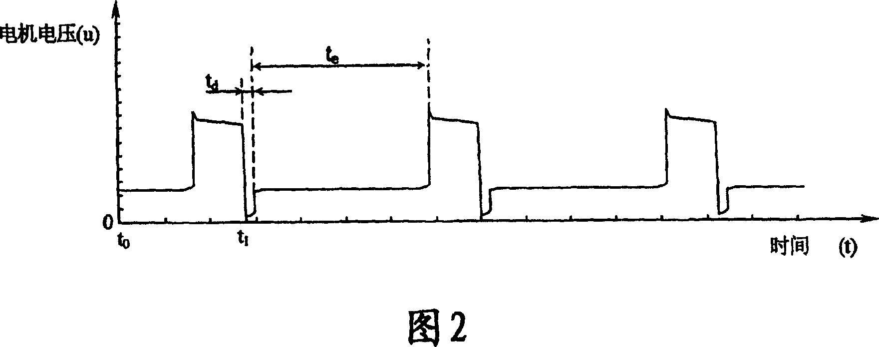
[0021] When the wire-feeding motor is working, an induced electromotive force will be generated when the power supply is cut off, and the induced electromotive force of the wire-feeding motor has a linear relationship with its speed. Therefore, accurate sampling of the induced electromotive force of the motor can accurately reflect the rotational speed of the motor. The voltage waveform at both ends of the wire feeding motor is shown in Figure 2. There is a t in the wire feed motor voltage waveform d and t e period. t d The time period is the release time of the energy stored in the armature winding of the wire-feeding motor. During this time period, the voltage at both ends of the wire-feeding motor is close to zero. During ...


PUM


Abstract

The system includes following parts: when sampling control device outputs control pulse, the sample and hold device is in use for sampling and holding the sampled signals; regulating device is in use for magnifying error of instruction signal and the said sampled and held signal; modulation device is in use for outputting signal of pulse width modulation, and the said signal is in use for controlling output from the drive unit based on signal outputted from the regulating device; the drive unit is in use for revolving driving the motor for delivering wire based on pulse signal outputted from the modulation device; the sample and control device is in use for outputting sample and control pulse signal before the moment when the drive unit provides energy to the motor for delivering wire; starting device is in use for controlling operating states of the modulation device and the drive unit.

Description

technical field [0001] The invention relates to a wire feeding speed regulating method and a wire feeding speed regulating system. Background technique [0002] In MIG arc welding, constant-speed wire feeding is usually used with a constant-voltage external characteristic power supply. Only by ensuring that the welding wire can be fed evenly can a regular droplet transfer occur. Therefore, the wire feeding system is a very important link in MIG arc welding. The change of wire feeding speed will affect the change of welding current. Therefore, the stability of wire feeding speed will directly affect the stability of welding process and welding process. Seam forming. [0003] In the actual use of welding equipment, the voltage of the grid often fluctuates greatly, and the wire feeding resistance is affected by many factors such as the quality of the welding wire and the wire feeding catheter, and the change is also great. [0004] When the DC motor is running, its armature w...

Claims


Application Information

Patent Timeline
Patent Type & Authority Applications(China)
IPC IPC(8): H02P7/00H02P7/06H02P7/28B23K9/133
Inventor 翟玉喜郭怀书
Owner PANASONIC WELDING SYST TANGSHAN
Why Eureka
Try Eureka