Three level power converter

A technology of power transformation devices and switching elements, applied in the direction of output power conversion devices, circuits, electrical components, etc., can solve problems such as difficult suppression, insufficient cooling of semiconductor components, etc., achieve balanced temperature rise, and improve cooling efficiency Effect

A technology of power transformation devices and switching elements, applied in the direction of output power conversion devices, circuits, electrical components, etc., can solve problems such as difficult suppression, insufficient cooling of semiconductor components, etc., achieve balanced temperature rise, and improve cooling efficiency Effect

CN101053145AActive Publication Date: 2007-10-10MITSUBISHI ELECTRIC CORP

Image

  • Three level power converter
  • Three level power converter
  • Three level power converter

Examples


Embodiment approach 1

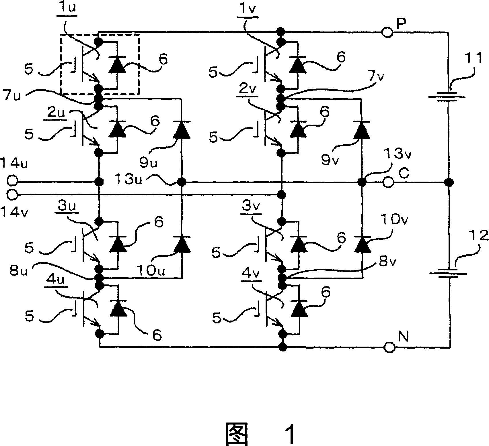
[0021] Fig. 1 is a circuit diagram using a three-level power transformer according to the present invention as a converter.

[0022] In FIG. 1 , first, the U-phase unit is sequentially connected with a first switching element 1u, a second switching element 2u, a third switching element 3u, and a fourth switching element 4u between the DC positive terminal P and the DC negative terminal N.

[0023] Similarly, in the V-phase unit, the first switching element 1v, the second switching element 2v, the third switching element 3v, and the fourth switching element 4v are sequentially connected between the DC positive terminal P and the DC negative terminal N.

[0024] Each of the switching elements 1u to 4u and 1v to 4v is composed of a self-arcing semiconductor element such as an IGBT (Insulated Gate Bipolar Transistor) or a GTO, for example. In Embodiment 1, the IGBT 5 and the freewheeling diode 6 connected in anti-parallel to the IGBT 5 are integrally modularized.

[0025] Between...

Embodiment approach 2

[0049] 9 is a plan view showing the arrangement of semiconductor elements on the cooler and the direction of cooling air in the three-stage power conversion device according to Embodiment 2 of the present invention. As in Embodiment 1 above, the configuration when used as an inverter having U-phase and V-phase inverter circuits is shown, and the circuit and operation are the same as in Embodiment 1 above.

[0050] As shown in FIG. 9 , the semiconductor element groups constituting the U-phase unit and the V-phase unit respectively are arranged on the heat receiving portion 15 of the cooler along the cooling air flow with their long sides oriented perpendicular to the cooling air flow direction. The first switching elements 1u, 1v and the fourth switching elements 4u, 4v are arranged adjacent to each other in the central portion of the heat receiving portion 15 . And, on one side of the first switching elements 1u, 1v and the fourth switching elements 4u, 4v, the second switchin...


PUM


Abstract

A three level power converter in which each phase comprises one unit having four switching elements (1u-4u) and two diodes (9u,10u) that are arranged along the flowing direction of cooling air with their long sides directed perpendicularly to the flowing direction of cooling air on the heat receiving section (15) of a cooler. First and second diodes (9u, 10u) are arranged in the center of the heat receiving section (15) whereas second and third switching elements (2u, 3u) having high heat generation loss are distributed while holding the central diode group between them, thus leveling temperature rise of respective switching elements.

Description

technical field [0001] The present invention relates to a three-level power conversion device including a plurality of semiconductor elements, a cooler, and the like. Background technique [0002] In the conventional 3-stage power transformation equipment, the switching elements and semiconductor elements such as diodes constituting the main circuit of each phase constitute one unit. a semiconductor element, at the same time connecting the first diode and the second diode in series, connecting the AC terminal at the connection point between the second semiconductor element and the third semiconductor element, and connecting the neutral point terminal at the connection point between the first diode and the second diode, The first diode is connected to the connection point of the first semiconductor element and the second semiconductor element, and the second diode is connected to the connection point of the third semiconductor element and the fourth semiconductor element. Ar...

Claims


Application Information

Patent Timeline
10 Oct 2007
Publication
CN101053145A
IPC
H02M7/48; H02M7/04; H01L23/467; H02M7/12
CPC
H02M7/483; H02M7/003; H02M7/487; H05K7/20909; H02M7/48; H01L23/467; H05K7/20
Inventors
田中毅; 中川良介