Control system for modular robot based on CAN bus

A CAN bus and control system technology, applied in the field of modular articulated robot control systems, can solve the problems of cost, installation and maintenance costs, and achieve the effects of short development cycle, reduced number of cables, and low cost

Inactive Publication Date: 2007-10-17
NORTHEASTERN UNIV
View PDF0 Cites 28 Cited by
  • Summary
  • Abstract
  • Description
  • Claims
  • Application Information

AI Technical Summary

Problems solved by technology

[0003] In order to overcome the shortcomings of existing robot control systems in terms of openness and reliability, as well as the shortcomings of high cost, installation and maintenance costs, the present invention provides a modular robot control system based on CAN bus, which uses CAN bus As the architecture of the

Method used


Image

  • Control system for modular robot based on CAN bus
  • Control system for modular robot based on CAN bus
  • Control system for modular robot based on CAN bus

Examples


Embodiment Construction

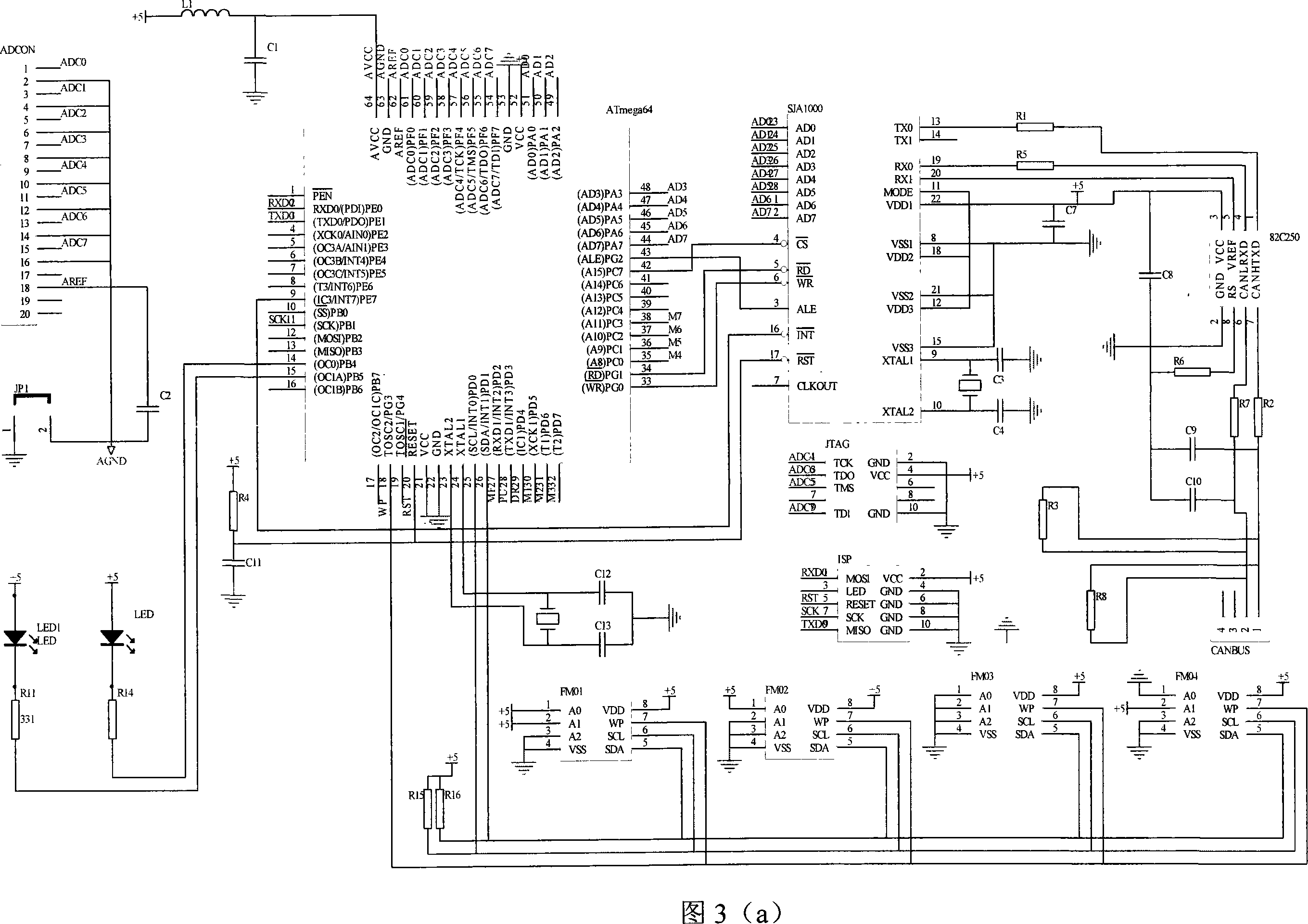
[0075] The circuit schematic diagram of the control module of the present invention is as shown in 2:

[0076] The main controller chip of the control module is ATmega64, which constitutes the communication interface circuit of the CAN bus with the CAN controller SJA1000 and the CAN bus driver PCA82C250; the pins 43, 42, 34, 33, 20, 9, 51, 50, 49 , 48, 47, 46, 45, 44 are respectively connected to pins 3, 4, 5, 6, 17, 16, 23, 24, 25, 26, 27, 28, 1, 2 of SJA1000; pin 13 of SJA1000 , 19, and 20 are connected to pins 1, 4, and 5 of PCA82C250 respectively; pins 7 and 6 of PCA82C250 are respectively connected to pins 1 and 2 of CANBAS through resistors R2 and R7; pins of four ferroelectric memories FM01-FM04 5, 6, and 7 are connected to pins 26, 25, and 18 of ATmega64 respectively; pins 1, 3, 5, and 9 of the JTAG interface are connected to pins 57, 55, 56, and 54 of ATmega64, as shown in Figure 3(b ) shown; the pins 1, 5, 7, and 9 of the ISP interface are connected to the pins 2, 2...


PUM


Abstract

The present invention relates to a modularized control system for an articulated robot, which is based on CAN bus. The present invention is characterized in that the control system comprises a PC, a CAN intelligence interface card, a plurality of control modules (wherein, each control module controls one articulation of the robot), and a CAN bus for connecting the modules and the CAN intelligence interface card. In the control system of the present invention, a two circuit CAN intelligence interface card is connected to the PC by an USB interface at one end, and is connected to the CAN bus by a CAN bus interface at the other end; the control module is connected to the CAN bus. The system and method of the present invention has excellent portability, short development cycle, low cost, regrouping property, fungible property, openness and high stability, and can execute on-line monitoring to robot.

Description

technical field [0001] The invention relates to a robot control system, in particular to a CAN bus-based modular joint robot control system. Background technique [0002] At present, the control systems of most robots are based on specific controlled objects, and are developed and designed using special hardware platforms, special systems and operating languages, and their structures are mostly closed. This makes it difficult for users or third-party developers to expand the functions of the robot's control system as needed, and to increase, decrease, and transplant the software and hardware of the control system. If the various functions of the control system are concentrated together without a clear division of structure and function, then a failure of one function will inevitably affect the reliability of the entire control system, and even cause the entire system to fail. The cost of the control system, installation and maintenance costs will increase accordingly. Ther...

Claims


Application Information

Patent Timeline
IPC IPC(8): B25J9/16B25J13/00G05B19/418
CPCY02P90/02
Inventor 韩清凯苏立娟侯硕
Owner NORTHEASTERN UNIV
Why Eureka
Try Eureka