Steel-concrete combined beam

A concrete beam and concrete technology, applied in the field of composite beams, can solve the problems of different thermal expansion coefficients and concrete creep, etc., achieve high fatigue resistance, improve stability, and avoid the effect of beam section prestress loss

Inactive Publication Date: 2007-10-17
SOUTHEAST UNIV
View PDF0 Cites 4 Cited by
  • Summary
  • Abstract
  • Description
  • Claims
  • Application Information

AI Technical Summary

Problems solved by technology

They have the problem of internal stress of beams caused by factors such as steel and concrete due to different thermal expansion coefficients and concrete creep.

Method used


Image

  • Steel-concrete combined beam
  • Steel-concrete combined beam
  • Steel-concrete combined beam

Examples


Embodiment 1

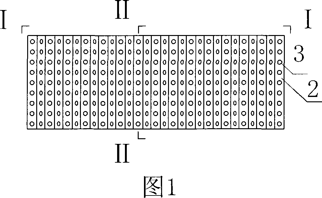
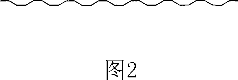
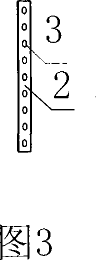
[0019] Embodiment 1 A steel-concrete composite beam, comprising a concrete beam 1, a corrugated steel plate 2 is arranged in the concrete beam 1, a hole 3 is arranged on the corrugated steel plate 2, and a stirrup is arranged in the hole 3 on the corrugated steel plate 2 5. A steel plate 6 is provided at the bottom of the corrugated steel plate 2, and a shear nail 7 is provided at the bottom of the steel plate 6.

[0020] In this embodiment, the concrete beam 1 is an I-shaped beam, and the corrugated steel plate in the steel-concrete composite beam is connected with the concrete through three kinds of shear pins: the first is that the concrete 1 fills the holes on the corrugated steel plate form a shear pin; the second is to pass the stirrup 5 through the hole of the punched corrugated steel plate 2 to form a reinforced concrete shear pin; the third is to form a punched corrugated steel plate 2 and a steel plate 6 welded with a shear nail 7 Welded together to form.

Embodiment 2

[0021] Embodiment 2 A steel-concrete composite beam, comprising a concrete beam 1, a corrugated steel plate 2 is arranged in the concrete beam 1, a hole 3 is arranged on the corrugated steel plate 2, and a stirrup is arranged in the hole 3 on the corrugated steel plate 2 5. A steel plate 6 is provided at the bottom of the corrugated steel plate 2, a shear stud 7 is provided at the bottom of the steel plate 6, and a prestressed steel bar 4 is provided in the concrete beam 1, and the prestressed steel bar 4 is located below the corrugated steel plate 2.

[0022] In this embodiment, the concrete beam 1 is a T-shaped beam, and the prestressed steel bars 4 provided in the concrete beam 1 can be arranged in a straight line, broken line or curve.


PUM


Abstract

The invention discloses a steel-concrete combination beam ,including a concrete beam (1), characterized in that a waveform steel plate (2) is arranged in concrete beam (1), because the waveform steel plate has advantage of light quality, high shear resistant yield strength, and the waveform steel web plate can not resist acting axial force and so that can efficiently exert prestressing force for concrete beam, and the waveform steel plate can not restrain the deformation caused by slow changing and drying shrinkage of the enwrapped concrete, avoiding the prestress damage of beam cross section caused by constraining action of steel plate, additionally, the shear resistant connecting key formed naturally between the concrete and the waveform steel plate joins them into a whole, the beam has good integrity and high fatigue resistance, so the invention can improve stability of whole structure for the concrete beam.

Description

technical field [0001] The invention relates to a composite beam, in particular to a steel-concrete composite beam. Background technique [0002] Existing steel-concrete composite beams generally have the following types: steel-concrete structure, steel pipe concrete structure, outsourcing concrete structure, and pre-bent composite beam structure. A common feature of the above methods is to combine steel and concrete. They have the problem of internal stress of the beam caused by factors such as the difference in thermal expansion coefficient between steel and concrete, and the creep of concrete. Contents of the invention [0003] The invention provides a steel-concrete composite beam with strong overall structural stability. [0004] The present invention adopts following technical scheme: [0005] A steel-concrete composite beam includes a concrete beam in which a corrugated steel plate is arranged. [0006] Compared with the prior art, the present invention has the f...

Claims


Application Information

Patent Timeline
Patent Type & Authority Applications(China)
IPC IPC(8): E04C3/293
Inventor 万水肖江声廖济柙李建军柴干朱坤宁
Owner SOUTHEAST UNIV
Why Eureka
Try Eureka